A Robot Controller With The Compute Module 5

The regular Raspberry Pi line is a flexible single-board computer, but sometimes you might find yourself wishing for a form factor that was better designed for installation into a greater whole. This is why the Compute Module variants exist. Indeed, leveraging that intention, [Hans Jørgen Grimstad] has used the powerful Compute Module 5 as the heart of his “Overlord” robot controller.

The Compute Module 5 offers a powerful quad-core 64-bit ARM chip running at 2.4 GHz, along with anywhere from 2 to 16GB of RAM. You can also get it with WiFi and Bluetooth built in onboard, and it comes with a wide range of I2C, SPI, UART, and GPIO pins to serve whatever ends you envision for them. It’s a whole lot of capability, but the magic is in what you do with it.

For [Hans], he saw this as a powerful basis for a robot controller. To that end, he built a PCB to accept the Compute Module 5, and outfit it with peripherals suited to robotics use. His carrier board equips it with an MCP2515 CAN controller and a TJA1051 CAN transceiver, ideal for communicating in a timely manner with sensors or motor controllers. It also has a 9-axis BNO055 IMU on board, capable of sensor fusion and 100Hz updates for fine sensing and control. The board is intended to be easy to use with hardware like Xiaomi Cybergear motors and Dynamixels servos. As a bonus, there is power circuitry on board to enable it to run off anything from 5 to 36V. While GPIOs aren’t exposed, [Hans] notes that you can even pair it with a second Pi if you want to use GPIOs or camera ports or do any other processing offboard.

If you’re looking for a place to start for serious robot development, the Overlord board has plenty of capability. We’ve explored the value of the Compute Module 5 before, too. Meanwhile, if you’re cooking up your own carrier boards, don’t hesitate to let the tipsline know!

Raspberry Pi Compute Module 5 Seen In The Wild

Last Thursday we were at Electronica, which is billed as the world’s largest electronics trade show, and it probably is! It fills up twenty airplane-hangar-sized halls in Munich, and only takes place every two years.

And what did we see on the wall in the Raspberry Pi department? One of the relatively new AI-enabled cameras running a real-time pose estimation demo, powered by nothing less than a brand-new Raspberry Pi Compute Module 5. And it seemed happy to be running without a heatsink, but we don’t know how much load it was put under – most of the AI processing is done in the camera module.

We haven’t heard anything about the CM5 yet from the Raspberry folks, but we can’t imagine there’s all that much to say except that they’re getting ready to start production soon. If you look really carefully, this CM5 seems to have mouse bites on it that haven’t been ground off, so we’re speculating that this is still a pre-production unit, but feel free to generate wild rumors in the comment section.

The test board looks very similar to the RP4 CM demo board, so we imagine that the footprint hasn’t changed. (Edit: Oh wait, check out the M2 slot on the right-hand side!)

The CM4 was a real change for the compute module series, coming with a brand-new pinout that enabled them to break out more PCIe lanes. Despite the special connectors, it wasn’t all that hard to work with if you’re dedicated. So if you need more computing power in that smaller form factor, we’re guessing that you won’t have to wait all that much longer!

Thanks [kuro] for the tip, and for walking around Electronica with me.

A Dedicated GPU For Your Favorite SBC

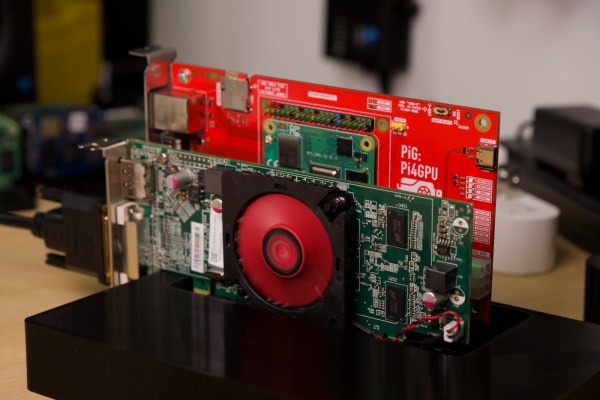
The Raspberry Pi is famous for its low cost, versatile and open Linux environment, and plentiful I/O, making it a perfect device not only for its originally-intended educational purposes but for basically every hobbyist from gardeners to roboticists to amateur radio operators. Most builds tend to make use of the GPIO pins which allow easy connections to various peripherals and sensors, but the Pi also supports PCI devices which means that, in theory, it could use a GPU in much the same way that a modern computer would. After plenty of testing and development, [Jeff Geerling] brings us this custom graphics card interface for the Raspberry Pi.

The testing for all of these graphics cards has been done with a Pi Compute Module 4 and the end result is an interface device which looks much like a graphics card itself. It splits the PCI bus out onto a more familiar x16 slot connector and adds physical connections for power, USB, and Ethernet. When plugged into the carrier board, the Compute Module can be attached to any of a number of graphics cards, including the latest and highest-end of Nvidia and AMD offerings.

Perhaps unsurprisingly, though, the 4090 and 7900 cards don’t work with the Raspberry Pi. This is partially due to the 32-bit limitations of the Pi and other memory mapping issues, but even after attempting some workarounds Nvidia’s cards aren’t open-source enough to test properly (although the card is recognized by the Pi) and AMD’s drivers crash the system even after compiling a custom kernel. [Jeff] did find an Nvidia card that worked, although it requires using the USB interface and second-hand cards are selling for around $3000 USD. For a more economical choice there are some other graphics cards that he was eventually able to get working, albeit not with perfect performance, including some of the ones we’ve seen him test already.

Continue reading “A Dedicated GPU For Your Favorite SBC”

Sketch of the two proprietary carriers showing their differences - one of them has a cutout under the antenna, while the other one does not.

Design Your CM4 Carrier With WiFi Performance In Mind

The Raspberry Pi Compute Module 4 has a built-in WiFi antenna, but that doesn’t mean it will work well for you – the physical properties of the carrier board impact your signal quality, too. [Avian] decided to do a straightforward test – measuring WiFi RSSI changes and throughput with a few different carrier boards. It appears that the carriers he used were proprietary, but [Avian] provides sketches of how the CM4 is positioned on these.

There’s two recommendations for making WiFi work well on the CM4 – placing the module’s WiFi antenna at your carrier PCB’s edge, and adding a ground cutout of a specified size under the antenna. [Avian] made tests with three configurations in total – the CMIO4 official carrier board which adheres to both of these rules, carrier board A which adheres to neither, and carrier board B which seems to be a copy of board A with a ground cutout added.

Graph plotting WiFi RSSI for each of the three carriers in each of the six locations. CMIO4 consistently outperforms both, while carrier B outperforms the carrier A, but by a more narrow margin.After setting up some test locations and writing a few scripts for ease of testing, [Avian] recorded the experiment data. Having that data plotted, it would seem that, while presence of an under-antenna cutout helps, it doesn’t affect RSSI as much as the module placement does. Of course, there’s way more variables that could affect RSSI results for your own designs – thankfully, the scripts used for logging are available, so you can test your own setups if need be.

If you’re lucky to be able to design with a CM4 in mind and an external antenna isn’t an option for you, this might help in squeezing out a bit more out of your WiFi antenna. [Avian]’s been testing things like these every now and then – a month ago, his ESP8266 GPIO 5V compatibility research led to us having a heated discussion on the topic yet again. It makes sense to stick to the design guidelines if WiFi’s critical for you – after all, even the HDMI interface on Raspberry Pi can make its own WiFi radio malfunction.

A pinout diagram of the new Pi 4, showing all the alternate interfaces available.

Did You Know That The Raspberry Pi 4 Has More SPI, I2C, UART Ports?

We’ve gotten used to the GPIO-available functions of Raspberry Pi computers remaining largely the same over the years, which is why it might have flown a little bit under the radar: the Raspberry Pi 4 has six SPI controllers, six I2C controllers, and six UARTs – all on its 40-pin header. You can’t make use of all of these at once, but with up to four different connections wired to a single pin you can carve out a pretty powerful combination of peripherals for your next robotics, automation or cat herding project.

The datasheet for these peripherals is pleasant to go through, with all the register maps nicely laid out – even if you don’t plan to work with the register mappings yourself, the maintainers of your preferred hardware enablement libraries will have an easier time! And, of course, these peripherals are present on the Compute Module 4, too. It might feel like such a deluge of interfaces is excessive, however, it lets you achieve some pretty cool stuff that wouldn’t be possible otherwise.

Having multiple I2C interfaces helps deal with various I2C-specific problems, such as address conflicts, throughput issues, and mixing devices that support different maximum speeds, which means you no longer need fancy mux chips to run five low-resolution Melexis thermal camera sensors at once. (Oh, and the I2C clock stretching bug has been fixed!) SPI interfaces are used for devices with high bandwidth, and with a few separate SPI ports, you could run multiple relatively high-resolution displays at once, No-Nixie Nixie clock style.

As for UARTs, the Raspberry Pi’s one-and-a-half UART interface has long been an issue in robotics and home automation applications. With a slew of devices like radio receivers/transmitters, LIDARs and resilient RS485 multi-drop interfaces available in UART form, it’s nice that you no longer have to sacrifice Bluetooth or a debug console to get some fancy sensors wired up to your robot’s brain. You can enable up to six UARTs. Continue reading “Did You Know That The Raspberry Pi 4 Has More SPI, I2C, UART Ports?”

This Raspberry Pi Mini ITX Board Has Tons Of IO

The Raspberry Pi now comes in a wide variety of versions. There are tiny little Zeros, and of course the mainstream-sized boards. Then, there’s the latest greatest Compute Module 4, ready to slot on to a carrier board to break out all its IO. The Seaberry is one such design, as demonstrated by [Jeff Geerling], giving the CM4 a Mini ITX formfactor and a ton of IO. (Video embedded after the break.)

The Seaberry sports a full-sized x16 PCI-E port, with only 1x bandwidth but capable of holding full-sized cards. There’s also four mini-PCI-E slots along the top, with four M.2 E-key slots hiding underneath. The board then has a M.2 slot in the middle for NVME drives, and x1 PCI-E slot hanging off the side.

Ports include a USB 2.0, a Cisco-style serial console port, two HDMI ports, and a Gigabit Ethernet jack. Two seperate 12V connectors are provided allowing for a redundant power supply setup, which can be made triple redundant with the addition of the right Power-over-Ethernet hardware. Naturally, the Seaberry also features the usual 40-pin GPIO header, the 14-pin CM4 IO header, as well as the usual DSI, CSI and RTC hookups.

The Mini ITX design is a particular boon. The Seaberry can easily be slapped into a mini PC case, and the power button and activity LEDs work just like you’d expect.

In testing the board, [Jeff Geerling] filled up almost every slot, trying to see how many cards will run on an Compute Module 4 with 8GB of RAM. Throwing in an NVME SSD drive, several Coral TPUs for machine learning, multiple network cards and a SATA interface caused no problems.

Not everything worked due to driver limitations, but everything enumerated on the bus just fine. [Jeff’s] earlier work paid dividends here. His previous attempts trying to get GPUs working on the platform meant opening up an extended BAR space for PCI devices wasn’t a problem.

Further attempts involved adding in a 12-card carrier loaded up with 7 more TPUs, 5 more WiFi cards, and 3 more NVME drives. Outside of some kernel panics from excess NVME drives, the Pi CM4 was still able to detect everything, showing it can address more than 20 PCI-E devices without major issues.

Throwing so many devices at the Pi CM4 may not have an obvious application in the mainstream, but it’s sure to prove useful to someone. We’re certainly enjoying watching [Jeff] push the limits of what’s possible with the CM4, and we hope he gets GPUs working soon.

Continue reading “This Raspberry Pi Mini ITX Board Has Tons Of IO”

Pi Compute Module Is Love-child Of Raspberry And Arduino

The Raspberry Pi compute module is a powerful piece of hardware, especially for the price. With it, you get more IO than a normal Pi, plus the ability to design hardware around it that’s specifically tailored to your needs rather than simply to general-purpose consumers. However, this comes at the cost of needing a way to interface with it since the compute module doesn’t have the normal IO pins or ports, but [Timon] has come up with a handy development board for this module called the Piunora which solves a lot of these prototyping issues.

The development board expands the compute module to the familiar Arduino-like form factor, complete with IO headers, USB ports, and HDMI output. It doesn’t stop there, though. It has an M.2 connector, some built-in LEDs, a camera connector, and a few other features. It also opens up some other possibilities that would be difficult or impossible with a standard Pi 4, such as the ability to run the Pi as a USB gadget rather than as a host device which simplifies certain types of development, which is [Timon]’s intended function.

As a development board, this project has a lot of potential for the niche uses of the compute module when compared to the standard Raspberry Pi. For embedded applications it’s much easier to deploy, with the increased development costs as a tradeoff. If you’re still unsure what to do with the compute module 4, we have some reading for you. And Timon’s previous project is a great springboard.