Joshua Vasquez wrote a piece a couple of weeks ago about how his open source machine benefits greatly from having part numbers integrated into all of the 3D printed parts. It lets people talk exactly about which widget, and which revision of that widget, they have in front of them.
Along the way, he mentions that it’s also a good idea to have labels as an integrated part of the machine anywhere you have signals or connectors. That way, you never have to ask yourself which side is positive, or how many volts this port is specced for. It’s the “knowledge in the head” versus “knowledge in the world” distinction — if you have to remember it, you’ll forget it, but if it’s printed on the very item, you’ll just read it.
I mention this because I was beaten twice in the last week by this phenomenon, once by my own hand costing an hour’s extra work, and once by the hand of others, releasing the magic smoke and sending me crawling back to eBay.
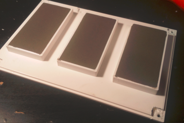
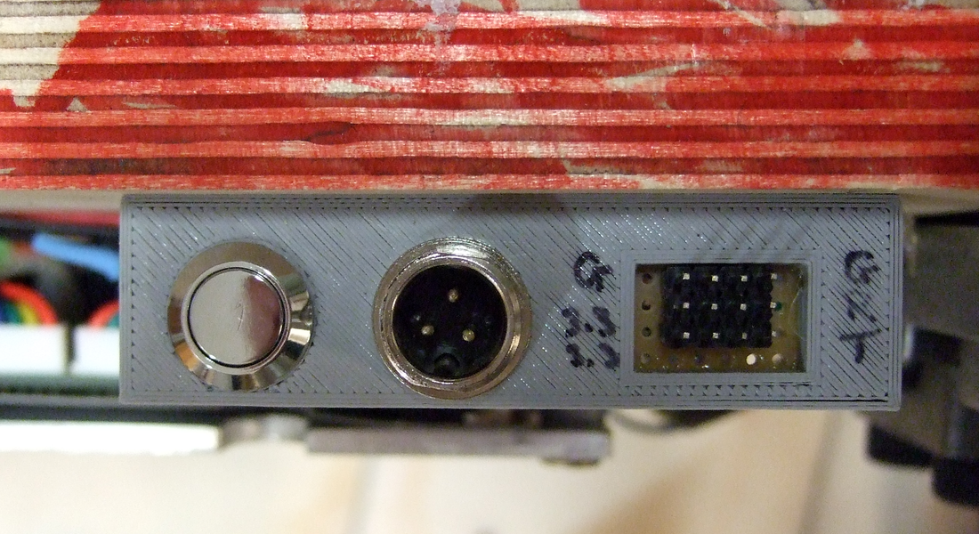 The first case is a 3D-printed data and power port, mounted on the underside of a converted hoverboard-transporter thing that I put together for last year’s Chaos Communication Congress. I was actually pretty proud of the design, until I wanted to reflash the firmware a year later.
I knew that I had broken out not just the serial lines and power rails (labelled!) but also the STM32 SWD programming headers and I2C. I vaguely remember having a mnemonic that explained how TX and RX were related to SCK and SDA, but I can’t remember it for the life of me. And the wires snake up under a heatsink where I can’t even trace them out to the chip. “Knowledge in the world”? I failed that, so I spent an hour looking for my build notes. (At least I had them.)
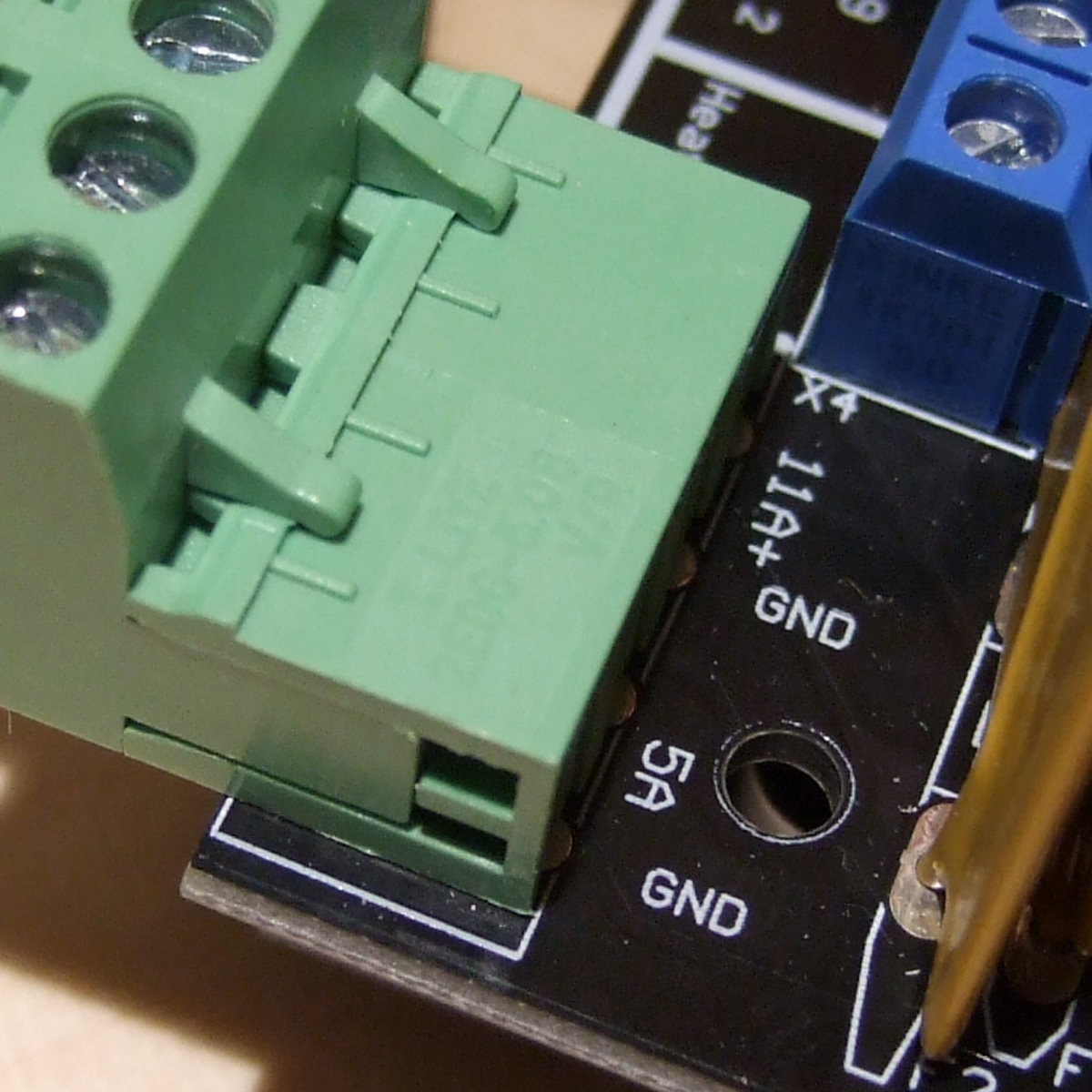 Then the smoke came out of an Arduino Mega that I was using with a RAMPS 1.4 board to drive a hot-wire cutting CNC machine. I’ve been playing around with this for a month now, and it was gratifying to see it all up and running, until something smelled funny, and took out a wall-wart power supply in addition to the Mega.
All of the parts on the RAMPS board are good to 36 V or so, so it shouldn’t have been a problem, and the power input is only labelled “5 A” and “GND”, so you’d figure it wasn’t voltage-sensitive and 18 V would be just fine. Of course, you can read online the tales of woe as people smoke their Mega boards, which have a voltage regulator that’s only good to 12 V and is powered for some reason through the RAMPS board even though it’s connected via USB to a computer. To be honest, if the power input were labelled 12 V, I still might have chanced it with 18 V, but at least I would have only myself to blame.
Part numbers are a great idea, and I’ll put that on my list of New Year’s resolutions for 2021. But better labels, on the device in question, for any connections, isn’t even going to wait the couple weeks until January. I’m changing that right now.