YouTuber The Science Furry has been attempting to make a split-anode magnetron and, after earlier failures, is having another crack at it. This also failed, but they’ve learned where to focus their efforts for the future, and it sure is fun to follow along.
The magnetron theory is simple enough, and we’ve covered this many times, but the split anode arrangement differs slightly from the microwave in your kitchen. The idea is to make a heated filament the cathode, so electrons are ejected from the hot surface by thermionic emission. These are forced into a spiral path using a perpendicular magnetic field. This is a result of the Lorentz force. A simple pair of magnets external to the tube is all that is needed for that. Depending on the diameter of the cavity and the gap width, a standing wave will be emitted. The anodes must be supplied with an alternating potential for this arrangement to work. This causes the electrons to ‘bunch up’ as they cross the gaps, producing the required RF oscillation. The split electrodes also allow an inductor to be added to tune the frequency of this standing wave. That is what makes this special.
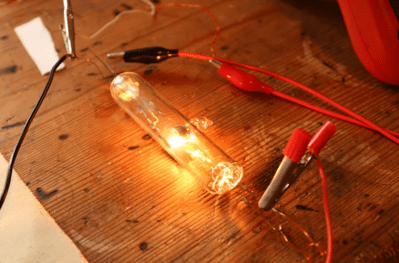
The construction starts with pre-made end seals with the tungsten wire electrode wire passing through. In the first video, they attempted to coat the cathode with barium nitrate, but this flaked off, ruining the tube. The second attempt replaces the coiled filament with a straight wire and uses a coating paste made from Barium Carbonate mixed with nitrocellulose in a bit of acetone. When heated, the nitrocellulose and the carbonate will decompose, hopefully leaving the barium coating intact. After inserting the electrode assembly into a section of a test tube and welding on the ends, the vacuum could be pulled and sealed off. After preheating the cathode, some gasses will be emitted into the vacuum, which is then adsorbed into a nearby titanium wire getter. At least, that’s the theory.
Upon testing, this second version burned out early on for an unknown reason, so they tried again, this time with an uncoated cathode. Measuring the emission current showed only 50 uA, which is nowhere near enough, and making the filament this hot caused it to boil off and coat the tube! They decide that perhaps this is one step too many and need to experiment with the barium coating by making simpler diode tubes to get the hang of the process!
If this stuff is over your head, you need a quick history lesson about the magnetron. Next check out this teardown. Finally, we have covered DIY magnetrons before, like this excellent DIY magnetron-powered plasma sputtering device. Yes, you read that correctly.