SDR Is At The Heart Of This Soup-Can Doppler Radar Set

Want to explore the world of radar but feel daunted by the mysteries of radio frequency electronics? Be daunted no more and abstract the RF complexities away with this tutorial on software-defined radar by [Luigi Cruz].

Taking inspiration from our own [Gregory L. Charvat], whose many radar projects have graced our pages before, this plunge into radar is spare on the budgetary side but rich in learning opportunities. The front end of the radar set is almost entirely contained in a LimeSDR Mini, a software-defined radio that can both transmit and receive. The only additional components are a pair of soup can antennas and a cheap LNA for the receive side. The rest of the system runs on GNU Radio Companion running on a Raspberry Pi; the whole thing is powered by a USB battery pack and lives in a plastic tote. [Luigi] has the radar set up for the 2.4-GHz ISM band, and the video below shows it being calibrated with vehicles passing by at known speeds.

True, the LimeSDR isn’t exactly cheap, but it does a lot for the price and lowers a major barrier to getting into the radar field. And [Luigi] did a great job of documenting his work and making his code available, which will help too. Continue reading “SDR Is At The Heart Of This Soup-Can Doppler Radar Set”

A Radar Module Teardown And Measuring Fan Speed The Hard Way

If you have even the slightest interest in microwave electronics and radar, you’re in for a treat. The Signal Path is back with another video, and this one covers the internals of a simple 24-GHz radar module along with some experiments that we found fascinating.

The radar module that [Shahriar] works with in the video below is a CDM324 that can be picked up for a couple of bucks from the usual sources. As such it contains a lot of lessons in value engineering and designing to a price point, and the teardown reveals that it contains but a single active device. [Shahriar] walks us through the layout of the circuit, pointing out such fascinating bits as capacitors with no dielectric, butterfly stubs acting as bias tees, and a rat-race coupler that’s used as a mixer. The flip side of the PCB has two arrays of beam-forming patch antennas, one for transmit and one for receive. After a few simple tests to show that the center frequency of the module is highly variable, he does a neat test using gimbals made of servos to sweep the signal across azimuth and elevation while pointing at a receiving horn antenna. This shows the asymmetrical nature of the beam-forming array. He finishes up by measuring the speed of a computer fan using the module, which has some interesting possibilities in data security as well as a few practical applications.

Even though [Shahriar]’s video tend to the longish side, he makes every second count by packing in a lot of material. He also makes complex topics very approachable, like what’s inside a million-dollar oscilloscope or diagnosing a wonky 14-GHz spectrum analyzer.

Continue reading “A Radar Module Teardown And Measuring Fan Speed The Hard Way”

Shmoocon: Delightful Doppler Direction Finding With Software Defined Radio

When it comes to finding what direction a radio signal is coming from, the best and cheapest way to accomplish the task is usually a Yagi and getting dizzy. There are other methods, and at Shmoocon this last weekend, [Michael Ossmann] and [Schuyler St. Leger] demonstrated pseudo-doppler direction finding using cheap, off-the-shelf software defined radio hardware.

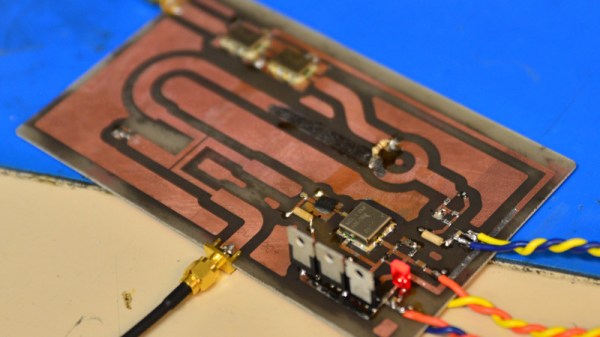
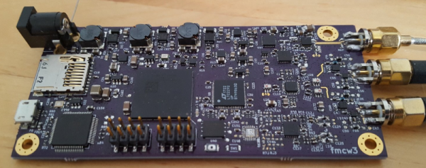
The hardware for this build is, of course, the HackRF, but this pseudo-doppler requires antenna switching. That means length-matched antennas, and switching antennas without interrupts or other CPU delays. This required an add-on board for the HackRF dubbed the Opera Cake. This board is effectively an eight-input antenna switcher using the state configurable timer found in the LPC43xx found on the HackRF.

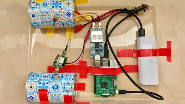
The key technique for pseudo-doppler is basically switching between an array of antennas mounted in a circle. By switching through these antennas very, very quickly — on the order of hundreds of thousands of times per second — you can measure the Doppler shift of a transmitter.

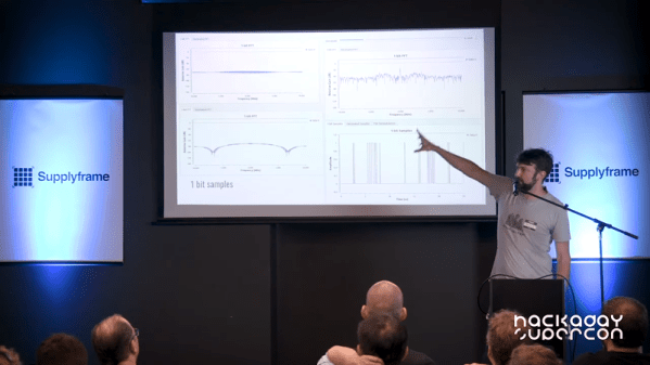
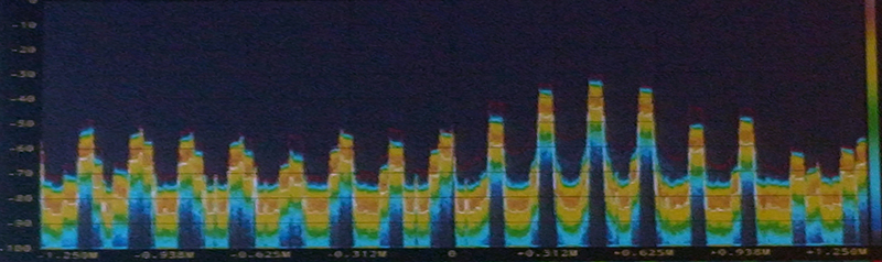
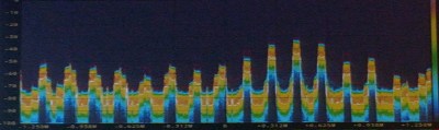
However, teasing out a distinct signal from a bunch of antennas virtually whizzing about isn’t exactly easy. If you look at what the HackRF an Opera Cake receive on a waterfall display, you’ll find a big peak around where you expect, and copies of that signal trailing off, separated by whatever your antenna switching frequency is. This was initially a problem for [Schuyler] and [Ossmann]’s experiments. Spinning the antennas at 20 kHz meant there was only 20 kHz difference in these copies, resulting in a mess that can’t be decoded. The solution was to virtually spin these antennas much faster, resulting in more separation, and a clean signal.

There are significant challenges when it comes to finding the direction of modern radio targets. Internet of Things things sometimes have very short packet duration, modulation interferes with antenna rotation, and packet detection must maintain the phase. That said, is this technique actually able to find the direction of IoT garbage devices? Yes, the demo on stage was simply finding the direction of one of the wireless microphones for the talk. It mostly worked, but the guys have some ideas for the future that would make this technique work a little better. They’re going to try phase demodulation instead of only frequency-based demodulation. They’re also going to try asymmetric antenna arrays and pseudorandom antenna switching. With any luck, this is going to become an easy and cheap way to do pseudo-doppler direction finding, all enabled by a few dollars in hardware and a laser-cut jig to hold a few antennas.

Measuring Airflow In An HVAC System

[Nubmian] wrote in to share his experiments with measuring airflow in an HVAC system. His first video deals with using with ultrasonic sensors. He found an interesting white paper that described measuring airflow with a single-path acoustic transit time flow meter. The question was, could he get the same effects with off-the-shelf components?

[Nubmian] created a rig using a pair of typical ultrasonic distance sensors. He detached the two transducers from the front of the PCB. The transducers were then extended on wires, with the “send” capsules together pointing at the “receive” capsules. [Nubmian] set the transducers up in a PVC pipe and blew air into it with a fan.

Continue reading “Measuring Airflow In An HVAC System”

Homemade 6 GHz Radar, V3

The third version of [Henrik Forstén] 6 GHz frequency-modulated continuous wave (FMCW) radar is online and looks pretty awesome. A FMCW radar is a type of radar that works by transmitting a chirp which frequency changes linearly with time. Simple continuous wave (CW) radar devices without frequency modulation cannot determine target range because they lack the timing mark necessary for accurately time the transmit and receive cycle in order to convert this information to range. Having a transmission signal modulated in frequency allows for the radar to have both a very high accuracy of range and also to measure simultaneously the target range and its relative velocity.

Like the previous versions, [Henrik] designed a four-layer pcb board and used his own reflow oven to solder all the ~350 components. This process, by itself, is a huge accomplishment. The board, much bigger than the previous versions, now include digital signal processing via FPGA.

[Henrik’s] radar odyssey actually started back in 2014, where his first version of the radar was detailed and shared in his blog. A year later he managed to solve some of the issues he had, design a new board with significant improvements and published it again. As the very impressive version three is out, we wonder what version four will look like.

In the video of [Henrik] riding a bicycle in a circle in front of the radar, we can see the static light posts and trees while he, seen as a small blob, roams around:

Continue reading “Homemade 6 GHz Radar, V3”

Doppler Module Teardown Reveals The Weird World Of Microwave Electronics

Oscillators with components that aren’t electrically connected to anything? PCB traces that function as passive components based solely on their shape? Slots and holes in the board with specific functions? Welcome to the weird and wonderful world of microwave electronics, brought to you through this teardown and analysis of a Doppler microwave transceiver module.

We’ve always been fascinated by the way conventional electronic rules break down as frequency increases. The Doppler module that [Kerry Wong] chose to pop open, a Microsemi X-band transceiver that goes for about $10 on eBay right now, has vanishingly few components inside. One transistor for the local oscillator, one for the mixer, and about three other passives are the whole BOM. That the LO is tuned by a barium titanate slug that acts as a dielectric resonator is just fascinating, as is the fact that PB traces can form a complete filter network just by virtue of their size and shape. Antennas that are coupled to the transceiver through an air gap via slots in the board are a neat trick too.

[Kerry] analyzes all this in the video below and shows how the module can be used as a sensor. If you need a little more detail on putting these modules to work, we’ve got some basic circuits you can check out.

Continue reading “Doppler Module Teardown Reveals The Weird World Of Microwave Electronics”

Fail Of The Week: Tracking Meteors With Weather Radio

It’s not hard to detect meteors: go outside on a clear night in a dark place and you’re bound to see one eventually. But visible light detection is limiting, and knowing that meteors leave a trail of ions means radio detection is possible. That’s what’s behind this attempt to map meteor trails using broadcast signals, which so far hasn’t yielded great results.

Passing jet’s Doppler signature

The fact that meteor trails reflect radio signals is well-known; hams use “meteor bounce” to make long-distance contacts all the time. And using commercial FM broadcast signals to map meteor activity isn’t new, either — we’ve covered the “forward scattering” technique before. The technique requires tuning into a frequency used by a distant station but not a local one and waiting for a passing meteor to bounce the distant signal back to your SDR dongle. Capturing the waterfall display for later analysis should show characteristic patterns and give you an idea of where and when the meteor passed.

[Dave Venne] is an amateur astronomer who turns his eyes and ears to the heavens just to see what he can find. [Dave]’s problem is that the commercial FM band in the Minneapolis area that he calls home is crowded, to say the least. He hit upon the idea of using the National Weather Service weather radio broadcasts at around 160 MHz as a substitute. Sadly, all he managed to capture were passing airplanes with their characteristic Doppler shift; pretty cool in its own right, but not the desired result.

The comments in the RTL-SDR.com post on [Dave]’s attempt had a few ideas on where this went wrong and how to improve it, including the intriguing idea of using 60-meter ham band propagation beacons. Now it’s Hackaday’s turn: any ideas on how to fix [Dave]’s problem? Sound off in the comments below.