Driver Board Makes Nixie Projects Easier Than Ever

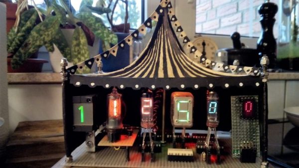
We know, we know — yet another Nixie clock. But really, this one has a neat trick: an easy to use, feature packed driver for Nixies that makes good-looking projects a snap.

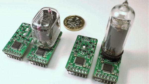
As cool as Nixies are — we’ll admit that to a certain degree, familiarity breeds contempt — they can be tricky to integrate. [dekuNukem] notes that aside from the high voltages, laying hands on vintage driver chips like the 7441 can be challenging and expensive. The problem was solved with about $3 worth of parts, including an STM32 microcontroller and some high-voltage transistors. The PCBs come in two flavors, one for the IN-12 and one for the IN-14, and connections for the SPI interface and both high- and low-voltage supplies are brought out to header pins. That makes the module easy to plug into a motherboard or riser card. The driver supports overdriving to accommodate poisoned cathodes, 127 brightness levels for smooth dimming, and a fully adjustable RBG backlight under the tube. See the boards in action in the video below, which features a nicely styled, high-accuracy clock.

From Nixie tachs to Nixie IoT clocks, [dekuNukem]’s boards should make creative Nixie projects even easier. But if you’re trying to drive a Nixie Darth Vader, you’re probably on your own.

Stepper Driver Module With Swappable Heatsinks

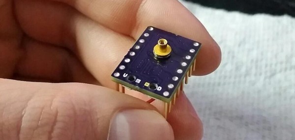
At first glance, [Dean Gouramanis]’s stepper driver module for 3D printers looks like just another RAMPS-compatible stepper board. Except, what could that gold-plated copper peg sticking out of the PCB possibly be? That would be [Dean]’s PowerPeg Thermal Management System that he built and entered in the Hackaday Prize competition for 2015, where it rocked its way into the Finals. It’s a thermal connector peg that attaches to a variety of heatsinks so you can swap in whatever sink fits the bill.

In the case of this project, [Dean] created a custom PCB that accommodates the PowerPeg connector, onto which the heat sink screws. Needless to say, he machined his own heatsinks to go with the pegs, though it looks like you could use any sink with enough surface contact that can be secured by the same #0-80 screw.

You shouldn’t be surprised that hackers obsess over heatsinks. This heatsink tester project we published helps determine which sink  to use. Another post gives all the ins and outs of ordering a custom heatsink.

Robotic Arm Rivals Industrial Counterparts

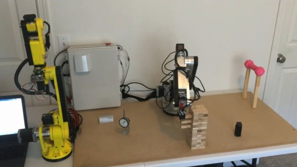
We’ve seen industrial robotic arms in real life. We’ve seen them in classrooms and factories. Before today, we’ve never mistaken a homemade robotic arm for one of the price-of-a-new-home robotic arms. Today, [Chris Annin] made us look twice when we watched the video of his six-axis robotic arm. Most of the DIY arms have a personal flare from their creator so we have to assume [Chris Annin] is either a robot himself or he intended to build a very clean-looking arm when he started.

He puts it through its paces in the video, available after the break, by starting with some stretches, weight-lifting, then following it up and a game of Jenga. After a hard day, we see the arm helping in the kitchen and even cracking open a cold one. At the ten-minute mark, [Chris Annin] walks us through the major components and talks about where to find many, many more details about the arm.

Many of the robotic arms on Hackaday are here by virtue of resourcefulness, creativity or unusual implementation but this one is here because of its similarity to the big boys.

Continue reading “Robotic Arm Rivals Industrial Counterparts”

Reed Organ MIDI Conversion Tickles All 88 Keys

What did you do in high school? Chances are it wasn’t anywhere near as cool as turning a reed organ into a MIDI device. And even if you managed to pull something like that off, did you do it by mechanically controlling all 88 keys? Didn’t think so.

A reed organ is a keyboard instrument that channels moving air over sets of tuned brass reeds to produce notes. Most are fairly complex affairs with multiple keyboards and extra controls, but the one that [Willem Hillier] scored for free looks almost the same as a piano. Even with the free instrument [Willem] is about $500 into this project. Almost half of the budget went to the solenoids and driver MOSFETs — there’s a solenoid for each key, after all. And each one required minor surgery to reduce the clicking and clacking sounds that don’t exactly contribute to the musical experience. [Willem] designed custom driver boards for the MOSFETs with 16 channels per board, and added in a couple of power supplies to feed all those hungry solenoids and the three Arduinos needed to run the show. The video below shows the organ being stress-tested with the peppy “Flight of the Bumblebee”; there’s nothing wrong with a little showing off.

[Willem]’s build adds yet another instrument to the MIDI fold. We’ve covered plenty before, from accordions to harmonicas and even a really annoying siren.

Continue reading “Reed Organ MIDI Conversion Tickles All 88 Keys”

A Command-Line Stepper Library With All The Frills

When you already know exactly where and how you’d like your motor to behave, a code-compile-flash-run-debug cycle can work just fine. But if you want to play around with a stepper motor, there’s nothing like a live interface. [BrendaEM]’s RDL is a generic stepper motor driver environment that you can flash into an Arduino. RDL talks to your computer or cell phone over serial, and can command a stepper-driver IC to move the motor in three modes: rotary, divisions of a circle, and linear. (Hence the acronumical name.) Best of all, the entire system is interactive. Have a peek at the video below.

The software has quite a range of capabilities. Typing “?” gets you a list of commands, typing “@” tells you where the motor thinks it is, and “h” moves the motor back to its home position. Rotating by turns, degrees, or to a particular position are simple. It can also read from an analog joystick, which will control the rotation speed forward and backward in real time.

Division mode carves the pie up into a number of slices, and the motor spins to these particular locations. Twelve, or sixty, divisions gives you a clock, for instance. Acceleration and deceleration profiles are built in, but tweakable. You can change microstepping on the fly, and tweak many parameters of the drive, and then save all of the results to EEPROM. If you’re playing around with a new motor, and don’t know how quickly it can accelerate, or what speeds it’s capable of, nothing beats playing around with it interactively.

Continue reading “A Command-Line Stepper Library With All The Frills”

Project Zero Finds A Graphic Zero Day

After finding the infamous Heartbleed vulnerability along with a variety of other zero days, Google decided to form a full-time team dedicated to finding similar vulnerabilities. That team, dubbed Project Zero, just released a new vulnerability, and this one’s particularly graphic, consisting of a group of flaws in the Windows Nvidia Driver.

Most of the vulnerabilities found were due to poor programming techniques. From writing to user provided pointers blindly, to incorrect bounds checking, most vulnerabilities were due to simple mistakes that were quickly fixed by Nvidia. As the author put it, Nvidia’s “drivers contained a lot of code which probably shouldn’t be in the kernel, and most of the bugs discovered were very basic mistakes.”

When even our mice aren’t safe it may seem that a secure system is unattainable. However, there is light at the end of the tunnel. While the bugs found showed that Nvidia has a lot of work to do, their response to Google was “quick and positive.” Most bugs were fixed well under the deadline, and google reports that Nvidia has been finding some bugs on their own. It also appears that Nvidia is working on re-architecturing their kernel drivers for security. This isn’t the first time we’ve heard from Google’s Project Zero, and in all honesty, it probably won’t be last.

Driving 16 WS2812B Strips With GPIOs And DMA

[Martin Hubáček] wrote in with his WS2812 LED library for the STM32F3 series processors. [Martin]’s library takes the same approach as [Paul Stoffregen]’s OctoWS2811 for the Teensy, and [Erich Styger]’s for the Freescale FRDM-K64F board. That is, it uses three DMA channels to get the signal out as fast as possible.

Continue reading “Driving 16 WS2812B Strips With GPIOs And DMA”