Importing EAGLE Projects Into KiCad 7, And How To Fix Them

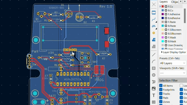
Migrating a PCB design from one CAD software package to another is no one’s favorite task. It almost never works cleanly. Often there are missing schematic symbols, scrambled PCB footprints, and plenty of other problems. Thankfully [shabaz] shows how to import EAGLE projects into KiCad 7 and fix the most common problems one is likely to encounter in the process. Frankly, the information couldn’t come at a better time.

This is very timely now that EAGLE has gone the way of the dodo. CadSoft EAGLE used to be a big shot when it came to PCB design for small organizations or individual designers, but six years after being purchased by Autodesk they are no more. KiCad 7 is a staggeringly capable open-source software package containing some fantastic features for beginner and advanced designers alike.

Of course, these kinds of tutorials tend to be perishable because software changes over time. So if you’re staring down a migration from EAGLE to KiCad and could use some guidance, there’s no better time than the present. [shabaz]’s video showing the process is embedded below.

Thanks to [problemchild68] for the tip!

Continue reading “Importing EAGLE Projects Into KiCad 7, And How To Fix Them”

They Used To Be A Big Shot, Now Eagle Is No More

There once was a time when to make a PCB in our community was to use CadSoft EAGLE, a PCB design package which neatly filled the entry level of that category with a free version for non-commercial designs. Upgrading it to the commercial version was fairly inexpensive, and indeed that was a path which quite a few designers making the step from hobby project to small production would take.

Then back in 2017, CadSoft were bought by Autodesk, and their new version 8 of the software changed its licensing model from purchase to rental. It became a product with a monthly subscription and an online side, and there began an exodus of users for whom pay-to-play meant too much risk of losing access to their designs. Now six years later the end has come, as the software behemoth has announced EAGLE’s final demise after a long and slow decline. Continue reading “They Used To Be A Big Shot, Now Eagle Is No More”

30-Year-Old Macintosh SE/30 Gets A Brand New Logic Board

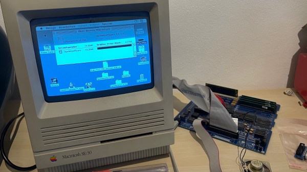
Some time ago, [Bolle] got the idea to redraw the Macintosh SE/30 schematics in Eagle. Progress was initially slow, but over the past month (and with some prodding and assistance from fellow forum frequenter [GeekDot]), he’s taken things a step further by creating a fully functional replacement Macintosh SE/30 logic board PCB.

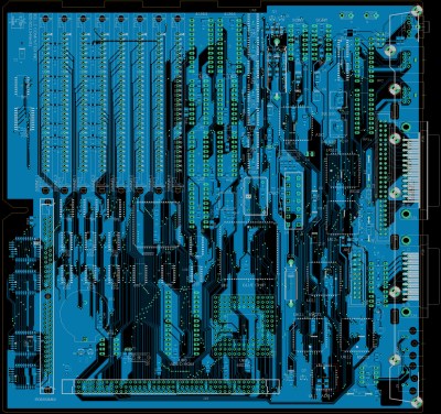
By using the available schematics, the project didn’t even require much reverse engineering. Though he plans for more modernization in later iterations, this design is largely faithful to the original components and layout, ensuring that it is at least basically functional. He did update the real time clock battery to a CR2032 and, as a benefit of redrawing all the traces, he was able to use a 4-layer PCB in place of the costly 6-layer from Apple’s design.

The board came back from fabrication looking beautiful in blue; and, once he had it soldered up and plugged in, the old Mac booted on the very first try! A copy-paste mistake with the SCSI footprints led to some jumper wire bodging in order to get the hard drive working, but that problem has already been fixed in the next revision. And, otherwise, he’s seen no differences from the original after a few hours of runtime.

Recreating old Macintosh logic boards almost seems like its own hobby these days. With the design and fabrication capabilities now accessible to hobbyists, even projects that were once considered professional work are in reach. If you’re interested in making your own PCB designs, there are many resources available to help you get started. Alternatively, we have seen other ways to modernize your classic Macs.

[Thanks to techknight for the tip!]

Plan Ahead: Roaming Charges Are A Killer

As the world gets more connected and computerized, it is easy to have an unintended consequence pop up and bite you. Especially because, so much of the time, today, things just work. The days of fretting over how to connect two computers, or how to store reasonable amounts of data are gone. Most of us never have to sift through assembly language programs finding three extra bytes to add a feature. Some Russian scientists recently found out about unintended consequences the hard way.

In the United States, the Eagle was long on the endangered species list, but apparently they have a similar problem in Russia. Scientists put a tracker on some migrating eagles in southern Russia and Kazakhstan. A few decades ago, this would have been a big technical challenge, but now you just use cellular technology and have the tracker text its location, right?

Continue reading “Plan Ahead: Roaming Charges Are A Killer”

These Wire Strippers Are Made From PCBs

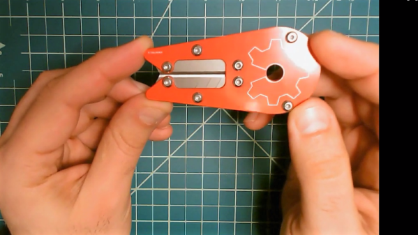
The rise in cheap PCB fabrication has made old-school prototyping methods such as wire wrapping somewhat passé, but it still has its place. And if you’re going to wire wrap, you’re going to want a quick and easy way to strip that fine Kynar-insulated wire. So why not use PCB material to make this handy wire-wrapping wire stripper?

The tool that [danielrp] built is pretty simple – just a pair of razor blades held together so as to form a narrow slot to cut insulation while leaving the conductor untouched. The body of the tool is formed of two PCBs, between which the blades are sandwiched. [danielrp] designed the outline of the PCBs in DraftSight, then exported a DXF into EAGLE to make the Gerbers. The fabricated boards needed a little post-processing, including tapping the holes on one side to accept the screws that hold the tool together. We were surprised that FR4 took the threads at all, but it seems to work for this low-torque application. The disposable snap-type blades were sandwiched between the PCBs and the gap between them adjusted for nick-free stripping. The video below shows the design and build process.

We always appreciate homemade tools, and the fact that you can get a stack of PCBs for almost nothing makes us wonder what else we could use them for. We recently saw them used in a unique word clock, and even turned into a folding circuit sculpture.

Continue reading “These Wire Strippers Are Made From PCBs”

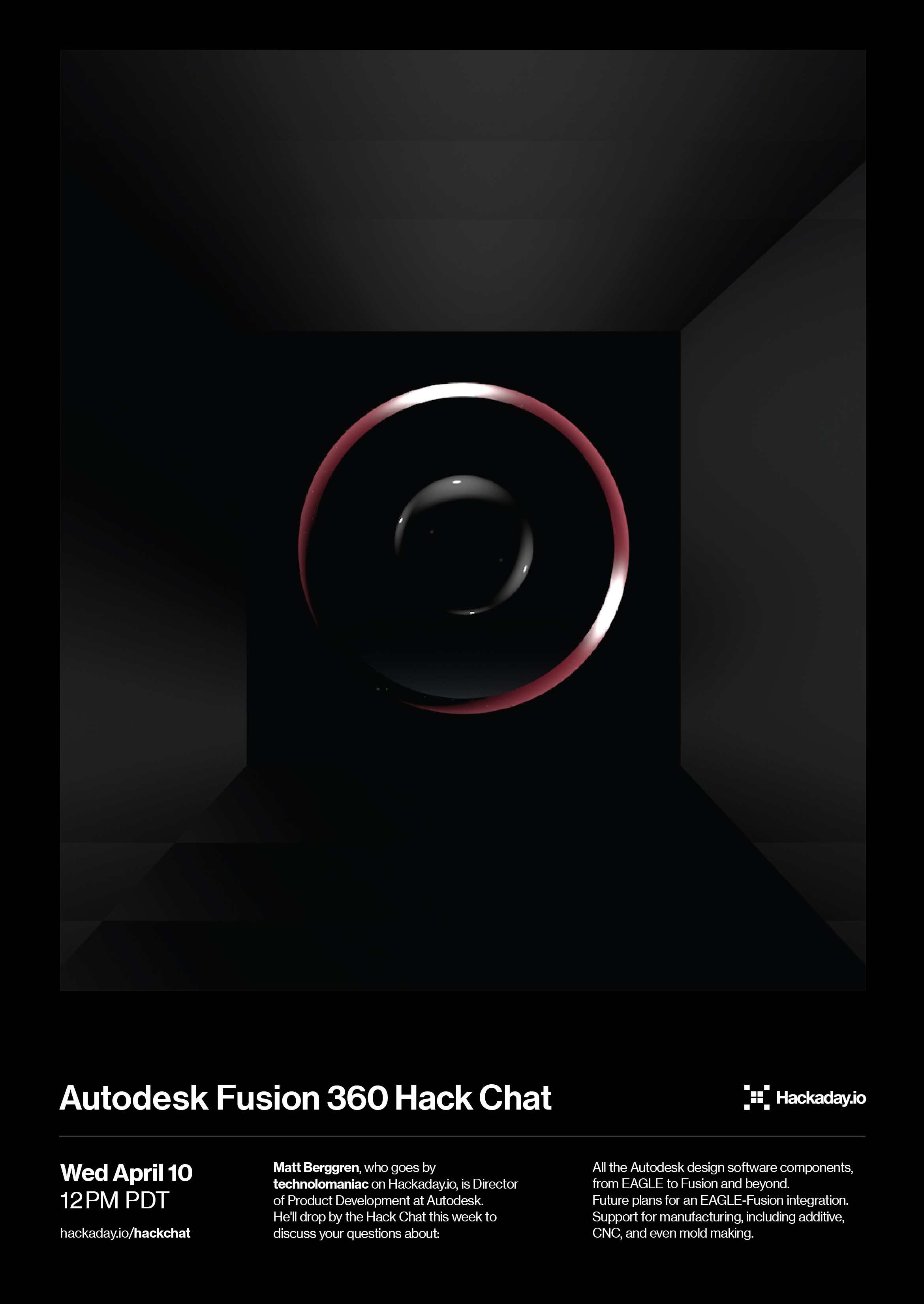
Autodesk Fusion 360 Hack Chat

Join us Wednesday at noon Pacific time for the Autodesk Fusion 360 Hack Chat!

Most of us have a collection of tools that we use for the various mechanical, electronic, and manufacturing tasks we face daily. But if you were asked to name one tool that stretches across all these spaces, Autodesk Fusion 360 would certainly spring to mind. Everyone from casual designers of 3D-printed widgets to commercial CNC machine shops use it as an end to end design solution, and anyone who has used it over the last year or so knows that the feature set in Fusion is expanding rapidly.

Matt, who goes by technolomaniac on Hackaday.io, is Director of Product Development for EAGLE, Tinkercad, and Fusion 360 at Autodesk. He’ll drop by the Hack Chat this week to discuss your questions about:

  • All the Autodesk design software components, from EAGLE to Fusion and beyond
  • Future plans for an EAGLE-Fusion integration
  • Support for manufacturing, including additive, CNC, and even mold making
  • Will there ever be “one design tool to rule them all?”

You are, of course, encouraged to add your own questions to the discussion. You can do that by leaving a comment on the Autodesk Fusion 360 Hack Chat page and we’ll put that in the queue for the Hack Chat discussion.

join-hack-chatOur Hack Chats are live community events in the Hackaday.io Hack Chat group messaging. This week we’ll be sitting down on Wednesday, April 10, at noon, Pacific time. If time zones have got you down, we have a handy time zone converter.

Click that speech bubble to the right, and you’ll be taken directly to the Hack Chat group on Hackaday.io. You don’t have to wait until Wednesday; join whenever you want and you can see what the community is talking about.

Adding Vector Art To Your Eagle Boards

Badgelife and the rise of artistic PCBs are pushing the envelope of what can be done with printed circuit boards. And if you’re doing PCB art, you really want to do it with vectors. This is a surprisingly hard problem, because very few software tools can actually do DXFs and SVGs properly. Never fear, because [TallDarknWeirdo] has the solution for you. It’s in Eagle, and it uses Illustrator and Inkscape, but then again this is a hard problem.

The demonstration article for this example is just a Christmas tree. It’s somewhat topical green soldermask is standard, FR4 looks like wood, and silver and gold and all that. [TallDarknWeirdo] first split up this vector art into its component pieces — soldermask, bare FR4, and copper — then imported it into Inkscape to make the SVGs. This was then thrown into an online tool that creates something Eagle can understand. The results are better than importing bitmaps, resulting in much cleaner lines in the finished board.

Quick word of warning before we get into this, though: if you’re reading this in 2019 or later, this info might be out of date. Autodesk should be releasing a vector import utility for Eagle shortly, and we’re going to be taking a deep dive into this tool and complaining until it works. Until then, this is the best way to get vector art into Eagle.

Oh, and [TallDarknWeirdo] is none other than [Bradley Gawthrop], who’s put more time in crimping wires than anyone else we know.