Here’s a fun exercise: take a list of the 20th century’s inventions and innovations in electronics, communications, and computing. Make sure you include everything, especially the stuff we take for granted. Now, cross off everything that can’t trace its roots back to the AT&T Corporation’s research arm, the Bell Laboratories. We’d wager heavily that the list would still contain almost everything that built the electronics age: microwave communications, data networks, cellular telephone, solar cells, Unix, and, of course, the transistor.
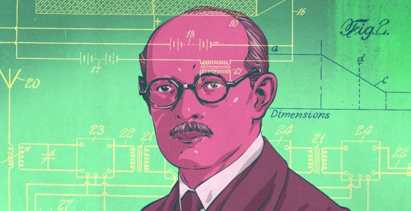
But is that last one really true? We all know the story of Bardeen, Brattain, and Shockley, the brilliant team laboring through a blizzard in 1947 to breathe life into a scrap of germanium and wires, finally unleashing the transistor upon the world for Christmas, a gift to usher us into the age of solid state electronics. It’s not so simple, though. The quest for a replacement for the vacuum tube for switching and amplification goes back to the lab of Julius Lilienfeld, the man who conceived the first field-effect transistor in the mid-1920s.
The first thing I ever built without a kit was a 5 V regulated power supply using the old LM309K. That’s a classic linear regulator like a 7805. While they are simple, they waste a lot of energy as heat, especially if the input voltage goes higher. While there are still applications where linear regulators make sense, they are increasingly being replaced by switching power supplies that are much more efficient. How do switchers work? Well, you buy a switching power supply IC, add an inductor and you are done. Class dismissed. Oh wait… while that might be the best way to do it from a cost perspective, you don’t really learn a lot that way.
In this installment of Circuit VR, we’ll look at a simple buck converter — that is a switching regulator that takes a higher voltage and produces a lower voltage. The first one won’t actually regulate, mind you, but we’ll add that in a future installment. As usual for Circuit VR, we’ll be simulating the designs using LT Spice.
Interestingly, LT Spice is made to design power supplies so it has a lot of Linear Technology parts in its library just for that purpose. However, we aren’t going to use anything more sophisticated than an op amp. For the first pass, we won’t even be using those.
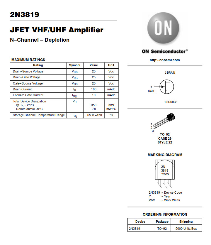
The 2N3819 is the archetypal general-purpose N-channel FET. (ON Semiconductor)
Over the recent weeks here at Hackaday, we’ve been taking a look at the humble transistor. In a series whose impetus came from a friend musing upon his students arriving with highly developed knowledge of microcontrollers but little of basic electronic circuitry, we’ve examined the bipolar transistor in all its configurations. It would however be improper to round off the series without also admitting that bipolar transistors are only part of the story. There is another family of transistors which have analogous circuit configurations to their bipolar cousins but work in a completely different way: the Field Effect Transistors, or FETs.
In a way it’s less pertinent to look at FETs in the way we did bipolar transistors, because while they are very interesting devices that power much of what you will do with electronics, you will encounter them as discrete components surprisingly rarely. Every CMOS device you deal with relies on FETs for its operation and every high-quality op-amp you throw a signal at will do so through a FET input, but these FETs are buried inside the chip and you’d be hard-pressed to know they were there if we hadn’t told you. You’d use a FET if you needed a high-impedance audio preamp or a low-noise RF amplifier, and FETs are a good choice for high-current switching applications, but sadly you will probably never have a pile of general-purpose FETs in the way you will their bipolar equivalents.
That said, the FET is a fascinating device. Join us as we take an in-depth look at their operation, and how and where you might use one.
FET basics
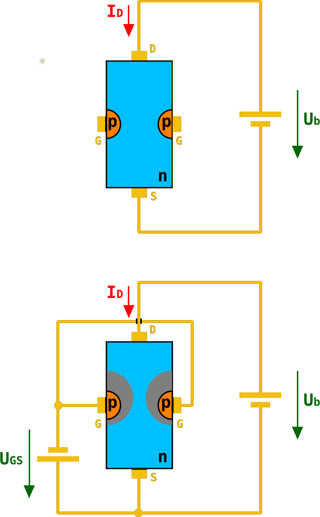
A diagram of an n-channel JFET. As the negative gate voltage on the p-type silicon decreases in the lower diagram, its electric field restricts the area through which electrons can flow in the n-type channel. Chtaube,(CC BY-SA 2.0 DE)
A basic FET has three terminals, a source (the source of electrons), a gate (the control terminal), and a drain (where electrons leave the device). These are analogous to the terminals on a bipolar transistor, in that the source fulfills a similar role to the emitter, the gate to the base, and the drain to the collector. Thus the three basic bipolar transistor circuit configurations have equivalents with a FET; common-emitter becomes common-source, common-base becomes common-gate, and an emitter follower becomes a source follower. It is dangerous to stretch the analogy between bipolar transistors and FETs too far, though, because of their different mode of operation. A closer similarity exists between a FET and a triode tube, if that helps.
The simplest FET for demonstration purposes has a piece of N-type semiconductor with source and drain connections at opposite ends, and a zone of P-type semiconductor deposited in its middle. This is referred to as an N-channel junction FET or JFET, because the channel through which current flows is N-type semiconductor, and because a diode junction exists between gate and channel. There are equivalent P-channel devices, just as there are PNP and NPN bipolar transistors.
Were you to bias an n-channel JFET as you would a bipolar transistor with a positive bias on its gate, the diode between gate and source would conduct, and the transistor would remain a diode with two cathode terminals. If however you give the gate a negative bias compared to the source, the diode becomes reverse-biased, and no current to speak of flows in the gate.
A characteristic of a reverse-biased diode is that it has a depletion zone between anode and cathode, an area in which there are no electrons. This is what causes the diode to no longer conduct, and the size of the depletion zone depends upon the size of the electric field that exists across it. If you’ve ever used a varicap diode, the capacitance between the two sides of this variable-width zone is the property you are exploiting.
In a FET, the depletion zone stretches from the gate region into the channel, and since its size can be adjusted by the gate voltage it can be used to “pinch” the remaining conductive region within the channel. Thus the area through which electrons can flow is controlled by the gate voltage, and thus the current that flows between drain and source is proportional to the gate voltage. We have an amplifier.
A simple FET radio receiver circuit showing FET biasing. The gate is biased at ground potential through the inductor, and the source is held above ground by the current in the 5K resistor. Herbertweidner [Public domain].In the JFET diagram above, the negative gate bias is represented by a battery. Tube enthusiasts may have encountered equipment that derives negative grid bias from a power supply, and you will find tube power units that include a -150 V rail for this purpose. In general though this is inconvenient in a FET circuit even though the voltage is lower, because of the extra cost of a negative regulator.. Instead the gate is held at a lower potential than the source by careful selection of a source resistor such that the current flowing through it brings the source up above ground, and a gate bias circuit that holds the gate close to ground. The base resistor chain from the bipolar circuit is for this reason often replaced with either a single resistor to ground, or a gate circuit with a very low DC resistance to ground such as an inductor.
MOSFETs, where the FET becomes more useful
Internal structure of an N-channel MOSFET. Fred the Oyster [Public domain].The JFET we have described is the simplest of field-effect devices, but it is not the one you will encounter most frequently. MOSFETs, short for Metal Oxide Semiconductor FETs, have a similar source, gate, and drain, but instead of relying on a depletion zone in a reverse-biased diode, they have a thin layer of insulation. The electric field from the gate acts across this insulation and pinches the conductive region in the channel through repulsion of electrons, with the same effect as it has in the JFET. It is beyond the scope of this piece to go into their mechanisms, but you will encounter two types of MOSFET: depletion mode devices that require the same negative bias as the JFET, and enhancement mode MOSFETS that require a positive bias.
Why would you use a FET?
So we’ve described the FET, and noted that while its mode of operation is different to that of a bipolar transistor it does a substantially similar job. Why would we use a FET then, what advantages does it offer us? The answer comes from the gate being insulated either by a depletion region in a JFET or by an insulating layer in a MOSFET. A FET is a voltage amplifier rather than a current amplifier, its input impedance is many orders higher than that of a bipolar transistor, and thus you will find FETs used in many applications that require a high impedance small-signal amplifier. The input of a high-performance op-amp will almost certainly be a FET, for example.
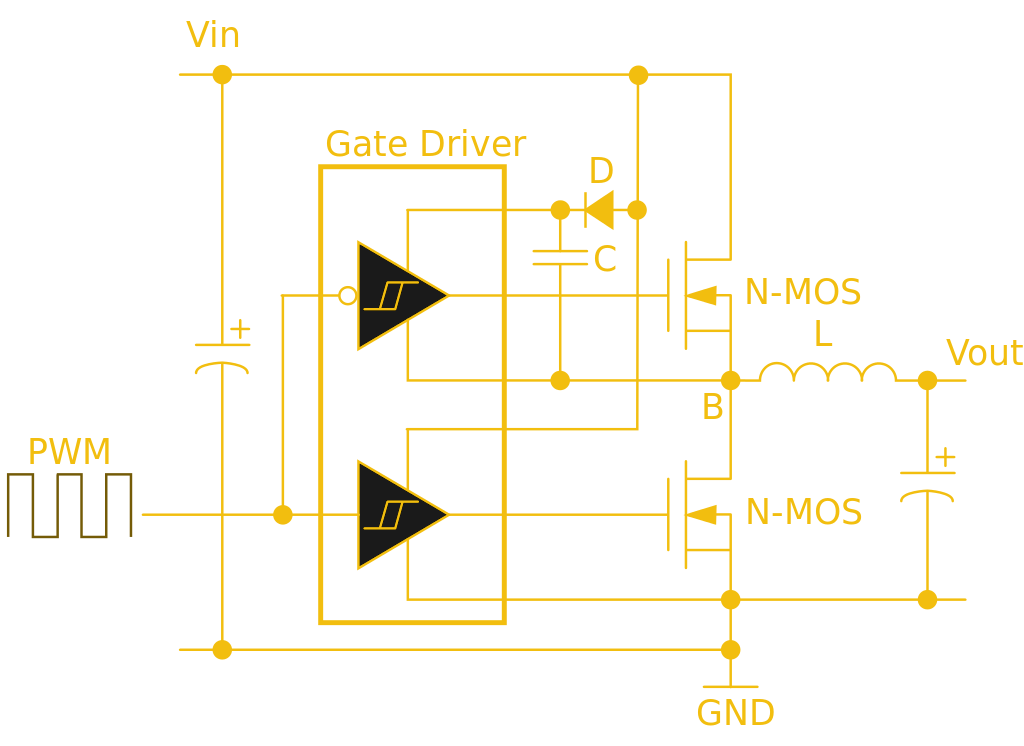
This half-bridge power MOSFET driver circuit uses a specialist gate driver IC with a pair of Schmidt buffers to deliver the initial surge required for a fast-turn-on time. Wdwd (CC BY 3.0).
The high input impedance has another effect less coupled to small signal work. Where a bipolar transistor requires significant base current to turn itself on, the corresponding FET requires almost none. Thus almost all complex integrated circuit logic devices are FET-based rather than bipolar because of the huge power saving that can be made by not needing to supply the base current demands of many thousands of bipolar transistors.
The same effect influences the choice of FETs for power switching, while a bipolar transistor’s base current is proportional to its collector current and thus it will need a significant driver, by contrast a power MOSFET requires virtually no standing gate current after an initial surge. A MOSFET power switch can thus be built requiring much less in the way of drive electronics and much more efficiently than a corresponding bipolar switch, and makes possible some of the tiny driver boards you might be used to for driving motors in your 3D printer, or your multirotor.
Through the course of this series you should have acquired a solid grounding in basic bipolar transistor principles, and now you should be able to add FETs to that knowledge base. We suggested you buy a bag of 2N3904s to experiment with in one of the previous articles, can we now suggest you do the same with a bag of 2N3819s?
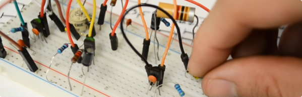
[Keystone Science] recently posted a video about building a theremin — you know, the instrument that makes those strange whistles when you move your hands around it. The circuit is pretty simple (and borrowed) but we liked the way the video explains the theory and even dives into some of the math behind resonant frequencies.
The circuit uses two FETs for the oscillators. An LM386 amplifier (a Hackaday favorite) drives a speaker so you can use the instrument without external equipment. The initial build is on a breadboard, but the final build is on a PCB and has a case.
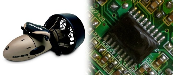
The Seadoo GTI Sea Scooter is a simple conveyance, consisting of a DC motor and a big prop in a waterproof casing. By grabbing on and firing the motor, it can be used to propel oneself underwater. However, [ReSearchITEng] had problems with their unit, and did what hackers do best – cracked it open to solve the problem.
Investigation seemed to suggest there were issues with the logic of the motor controller. The original circuit had a single FET, potentially controlled through PWM. The user interfaced with the controller through a reed switch, which operates magnetically. Using reed switches is very common in these applications as it is a cheap, effective way to make a waterproof switch.
It was decided to simplify things – the original FET was replaced with a higher-rated replacement, and it was switched hard on and off directly by the original reed switch. The logic circuitry was bypassed by cutting traces on the original board. [ReSearchITEng] also goes to the trouble of highlighting potential pitfalls of the repair – if the proper care isn’t taken during the reassembly, the water seals may leak and damage the electronics inside.
Overall it’s a solid repair that could be tackled by any experienced wielder of a soldering iron, and it keeps good hardware out of the landfill. For another take on a modified DC motor controller, check out the scooter project of yours truly.
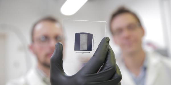
There are many obstacles in the way to turning carbon nanotubes into something useful. Materials engineers at the University of Wisconsin-Madison have now brought carbon nanotubes (CNTs) one step closer to becoming practically applicable for semiconductor electronics. In particular, the team managed to assemble arrays of carbon nanotube transistors that outperform their silicon-based predecessors.
I learned some basic electronics in high school physics class: resistors, capacitors, Kirchhoff’s law and such, and added only what was required for projects as I did them. Then around 15 years ago I decided to read some books to flesh out what I knew and add to my body of knowledge. It turned out to be hard to find good ones.
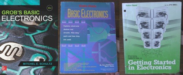
The electronics section of my bookcase has a number of what I’d consider duds, but also some gems. Here are the gems. They may not be the electronics-Rosetta-Stone for every hacker, but they are the rock on which I built my church and well worth a spot in your own reading list.
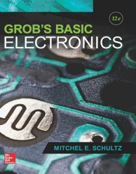
Grob’s Basic Electronics
Grob’s Basic Electronics 12th Edition
Grob’s Basic Electronics by Mitchel E Schultz and Bernard Grob is a textbook, one that is easy to read yet very thorough. I bought mine from a used books store. The 1st Edition was published in 1959 and it’s currently on the 12th edition, published in 2015. Clearly this one has staying power.
I refer back to it frequently, most often to the chapters on resonance, induction and capacitance when working on LC circuits, like the ones in my crystal radios. There are also things in here that I couldn’t find anywhere else, including thoroughly exhaustive online searches. One such example is the correct definitions and formulas for the various magnetic units: ampere turns, field intensity, flux density…
I’d recommend it to a high school student or any adult who’s serious about knowing electronics well. I’d also recommend it to anyone who wants to reduce frustration when designing or debugging circuits.
Series-Resonance calculations
Series-Resonance schematic
You can find the table of contents here but briefly it has all the necessary introductory material on Ohm’s and Kirchhoff’s laws, parallel and series circuits, and so on but to give you an idea of how deep it goes it also has chapters on network theorems and complex numbers for AC circuits. Interestingly my 1977 4th edition has a chapter on vacuum tubes that’s gone in the current version and in its place is a plethora of new ones devoted to diodes, BJTs, FETs, thyristors and op-amps.
You can also do the practice problems and self-examination, just to make sure you understood it correctly. (I sometimes do them!) But also, being a textbook, the newest edition is expensive. However, a search for older but still recent editions on Amazon turns up some affordable used copies. Most of basic electronics hasn’t changed and my ancient edition is one of my more frequent go-to books. But it’s not the only gem I’ve found. Below are a few more.


![A simple FET radio receiver circuit showing FET biasing. The gate is biased at ground potential through the inductor, and the source is held above ground by the current in the 5K resistor. Herbertweidner [Public domain].](https://hackaday.com/wp-content/uploads/2018/06/1kreiser_mit_fet.png)
![Internal structure of an N-channel MOSFET. Fred the Oyster [Public domain].](https://hackaday.com/wp-content/uploads/2018/04/n-channel_mosfet-svg1.png)