Reliable Frequency Reference From GPS

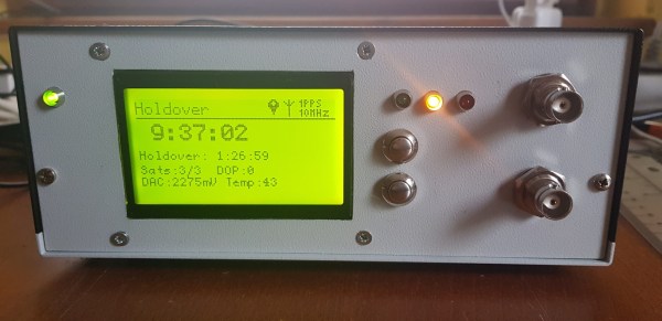
GPS technology is a marvel of the modern world. Not only can we reliably locate positions on the planet with remarkable accuracy and relatively inexpensive hardware, but plenty of non-location-based features of the technology are available for other uses as well. GPS can be used for things like time servers, since the satellites require precise timing in order to triangulate a position, and as a result they can also be used for things like this incredibly accurate frequency reference.

This project is what’s known as a GPSDO, or GPS-disciplined oscillator. Typically they use a normal oscillator, like a crystal, and improve its accuracy by pairing it with the timing signal from a GPS satellite. This one is a standalone model built by [Szabolcs Szigeti] who based the build around an STM32 board. The goal of the project was purely educational, as GPSDOs of various types are widely available, but [Szabolcs] was able to build exactly what he wanted into this one including a custom power supply, simple standalone UI, and no distribution amplifier.

The build goes into a good bit of detail on the design and operation of the device, and all of the PCB schematics and source code are available on the projects GitHub page if you want to build your own. There are plenty of other projects out there that make use of GPS-based time for its high accuracy, too, like this one which ties a GPS time standard directly to a Raspberry Pi.

Product Review: The TinySA, A Shirt-Pocket Sized Spectrum Analyzer

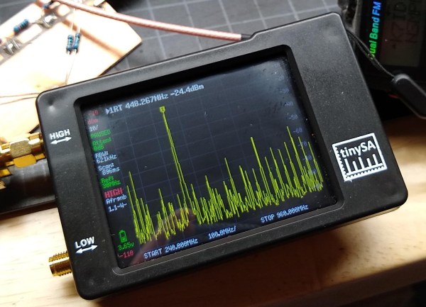
I suppose most of us have had the experience of going to the mailbox and seeing that telltale package in the white plastic bag, the sign that something has just arrived from China. This happened to me the other day, and like many of you it was one of those times when I puzzled to myself: “I wonder what I bought this time?”

With so many weeks or months between the time of your impulsive click on the “Buy Now” button on AliExpress or eBay and the slow boat from China actually getting the package to your door, it’s easy enough to forget what exactly each package contains. And with the price of goods so low, the tendency to click and forget is all the easier. That’s not necessarily a good thing, but I like surprises as much as the next person, so I was happy to learn that I was now the owner of a tinySA spectrum analyzer. Time for a look at what this little thing can do.

Continue reading “Product Review: The TinySA, A Shirt-Pocket Sized Spectrum Analyzer”

The Descendants Of Ancient Computers

Building computers from discrete components is a fairly common hobby project, but it used to be the only way to build a computer until integrated circuits came on the scene. If you’re living in the modern times, however, you can get a computer like this running easily enough, but if you want to dive deep into high performance you’ll need to understand how those components work on a fundamental level.

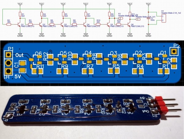
[Tim] and [Yann] have been working on replicating circuitry found in the CDC6600, the first Cray supercomputer built in the 1960s. Part of what made this computer remarkable was its insane (for the time) clock speed of 10 MHz. This was achieved by using bipolar junction transistors (BJTs) that were capable of switching much more quickly than typical transistors, and by making sure that the support circuitry of resistors and capacitors were tuned to get everything working as efficiently as possible.

The duo found that not only are the BJTs used in the original Cray supercomputer long out of production, but the successors to those transistors are also out of production. Luckily they were able to find one that meets their needs, but it doesn’t seem like there is much demand for a BJT with these characteristics anymore.

[Tim] also posted an interesting discussion about some other methods of speeding up circuitry like this, namely by using reach-through capacitors and Baker clamps. It’s worth a read in its own right, but if you want to see some highlights be sure to check out this 16-bit computer built from individual transistors.

Split Flap Clock Keeps Time Thanks To Custom Frequency Converter

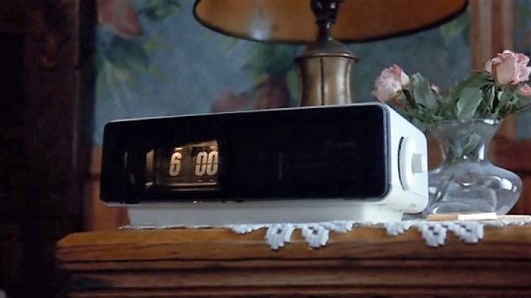
Why would anyone put as much effort into resurrecting a 1970s split-flap clock as [mitxela] did when he built this custom PLL frequency converter? We’re not sure, but we do like the results.

The clock is a recreation of the prop from the classic 1993 film, Groundhog Day, rigged to play nothing but “I Got You Babe” using the usual sound boards and such. But the interesting part was getting the clock mechanism keeping decent time. Sourced from the US, the clock wanted 120 VAC at 60 Hz rather than the 240 VAC, 50 Hz UK standard. The voltage difference could be easily handled, but the frequency mismatch left the clock running unacceptably slow.

That’s when [mitxela] went all in and designed a custom circuit to convert the 50 Hz mains to 60 Hz. What’s more, he decided to lock his synthesized waveform to the supply current, to take advantage of the long-term frequency control power producers are known for. The write-up goes into great detail about the design of the phase-locked loop (PLL), which uses an ATtiny85 to monitor the rising edge of the mains supply and generate the PWM signal that results in six cycles out for every five cycles in. The result is that the clock keeps decent time now, and he learned a little something too.

If the name [mitxela] seems familiar, it’s probably because we’ve featured many of his awesome builds before. From ludicrous-scale soldering to a thermal printer Polaroid to a Morse-to-USB keyboard, he’s always got something cool going on.

Listening To Mains Power, Part 2

The electricity on the power grid wherever you live in the world will now universally come to you as AC. That is to say that it will oscillate between positive and negative polarity many times every second. The frequency of 50 or 60Hz just happens to be within the frequency range for human hearing. There’s a lot more than this fundamental frequency in the spectrum on the power lines though, and to hear those additional frequencies better you’ll have to do a little bit of signal processing.

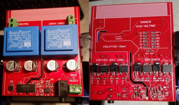
We first featured this build back when it was still in its prototyping phase, but since then it’s been completed and used successfully to find a number of anomalies on the local power grid. It takes inputs from the line, isolates them, and feeds them into MATLAB via a sound card where they can be analyzed for frequency content. It’s been completed, including a case, and there are now waterfall diagrams of “mystery” switching harmonics found with the device, plus plots of waveform variation over time. There’s also a video below that has these harmonics converted to audio so you can hear the electricity.

Since we featured it last, [David] also took some feedback from the comments on the first article and improved isolation distances on his PCB, as well as making further PCB enhancements before making the final version. If you’ve ever been curious as to what you might find on the power lines, be sure to take a look at the updates on the project’s page.

Continue reading “Listening To Mains Power, Part 2”

Help For High-Frequency Hobbyists

Dead-bug circuit building is not a pretty affair, but hey, function over form. We usually make them because we don’t have a copper circuit board available or the duty of making one at home is not worth the efforts and chemical stains.

[Robert Melville and Alaina G. Levine] bring to light a compromise for high-frequency prototypes which uses the typical FR4 blank circuit board, but no etching chemicals. The problem with high-frequency radio is that building a circuit on a breadboard will not work because there is too much added inductance and capacitance from the wiring that will wreak havoc on the whole circuit. The solution is not new, build your radio module on a circuit board by constructing “lands” over a conductive ground plane, where components can be isolated on the same unetched board.

All right, sometimes dead-bug circuits capture an aesthetic all their own, especially when they look like this and they do allow for a darned small package for one-off designs.

Tricking A Vintage Clock Chip Into Working On 50-Hz Power

Thanks to microcontrollers, RTC modules, and a plethora of cheap and interesting display options, digital clock projects have become pretty easy. Choose to base a clock build around a chip sporting a date code from the late 70s, though, and your build is bound to be more than run-of-the-mill.

This is the boat that [Fran Blanche] finds herself in with one of her ongoing projects. The chip in question is a Mostek MK50250 digital alarm clock chip, and her first hurdle was find a way to run the clock on 50 Hertz with North American 60-Hertz power. The reason for this is a lesson in the compromises engineers sometimes have to make during the design process, and how that sometimes leads to false assumptions. It seems that the Mostek designers assumed that a 24-hour display would only ever be needed in locales where the line frequency is 50 Hz. [Fran], however, wants military time at 60 Hz, so she came up with a circuit to fool the chip. It uses a 4017 decade counter to divide the 60-Hz signal by 10, and uses the 6-Hz output to turn on a transistor that pulls the 60-Hz output low for one pulse. The result is one dropped pulse out of every six, which gives the Mostek the 50-Hz signal it needs. Sure, the pulse chain is asymmetric, but the chip won’t care, and [Fran] gets the clock she wants. Pretty clever.

[Fran] has been teasing this clock build for a while, and we’re keen to see what it looks like. We hope she’ll be using these outsized not-quite-a-light-pipe LED displays or something similar.

Continue reading “Tricking A Vintage Clock Chip Into Working On 50-Hz Power”