Ultrasound refers to any audio signal above the range of human hearing. Generally that’s accepted as 20 kHz and up. Unlike electromagnetic signals, ultrasonics are still operating in a medium – generally the air around us. Plenty of animals take advantage of ultrasonics every day. So do hackers, makers, and engineers who have built thousands of projects based upon these high frequency signals. This weeks Hacklet is all about the best ultrasonic projects on Hackaday.io!
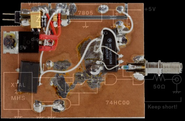
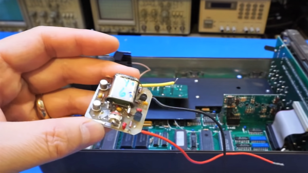
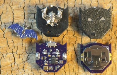 We start with [spambake] and World’s Smallest Bat Detector. [Spambake] is interested in bats. These amazing creatures have poor eyesight, but that doesn’t slow them down. Bats use echolocation to determine their surroundings. Ultrasonic chirps bounce off obstacles. The bat listens to the echos and changes its flight path accordingly. While we can’t hear most of the sounds bats make, electronics can. [Spambake] cooked this circuit up starting with a MEMs microphone. These microphones pick up human sounds, but unlike our ears, they can hear plenty above the 20 kHz range. The audio signal is passed through an amplifier which boosts the it up around 10,000 times. The signal is filtered and then used to trigger LEDs that indicate a bat is present. The final circuit works quite well! Check out [spambake’s] video to see the bat detector in action!
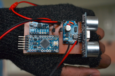 Next up is [Neil Movva] with Pathfinder – Haptic Navigation. Pathfinder uses ultrasonic transducers to perform echolocation similar to bats. The received data is then passed on to a human wearer. [Neil’s] idea is to use Pathfinder to help the visually disabled and blind navigate the world around them. Pathfinder was a 2015 Hackaday Prize finalist. The ultrasonic portion of Pathfinder uses the ubiquitous HC-SR04 distance sensor, which can be found for as little as $2 USD on eBay and Alibaba. These sensors send out a 60 kHz signal and listen for the echos. A microcontroller can then measure the time delay and determine the distance from the sensor to an obstacle. Finally the data is passed on to the user by a vibrating pager motor. [Neal] was kind enough to give a talk about Pathfinder at the 2015 Hackaday SuperCon.
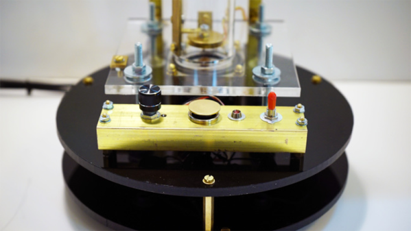
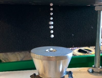 [HoboMunching] likes his ultrasonic devices ultra powerful, and that’s just what he’s got with Ultrasonic Levitation Rig. Inspired by a similar project from Mike, [HoboMunching] had to build his own levitation setup. Ultrasonic levitation used to be a phenomenon studied only in the laboratory. Cheap transducers designed for the industrial world have made this experiment practical for the home hackers. [HoboMunching] was able to use his rig to levitate up to 8 tiny balls on the nulls between the 28.5 kHz sound waves produced by his transducer. The speed of sound can be verified by measuring the distance between the balls. Purists will be happy to hear that [HoboMunching]’s circuit was all based upon the classic 555 timer.
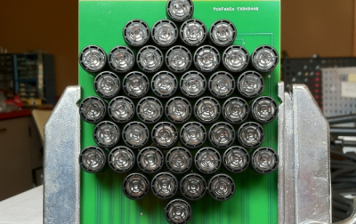 Finally we have [Alan Green] with Ultrasonic Directional Speaker V1. Most audio signals are not very directional, due to wavelength and practical limitations on speaker size. Ultrasonics don’t have this limitation. Couple this with the fact that ultrasonic signals can be made to demodulate in air, and you have the basis for a highly directional speaker setup. “Sound lasers” based on this system have been around for years, used in everything from targeted advertising to defensive weapons. [Alan] is just getting started on this project. Much of his research is based upon [Joe Pompei’s] work at the MIT media lab. [Alan] plans to use an array of ultrasonic transducers to produce a directional signal which will then demodulate and be heard by a human. This project has a hard deadline though: [Alan] plans to help his son [Mitchell] with a musical performance that is scheduled for May, 2016. The pair hope to have a prototype in place by March.
If you want to see more ultrasonic projects, check out our new ultrasonic projects list! If I missed your project, don’t be shy! Just drop me a message on Hackaday.io. That’s it for this week’s Hacklet. As always, see you next week. Same hack time, same hack channel, bringing you the best of Hackaday.io!