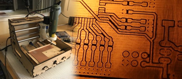
A funny thing happened on [Marco Rep]’s way to upgrading his 3D printer. Instead of ending up with a heated bed, his $300 3D printer can now etch 0.2-mm PCB traces. And the results are pretty impressive, all the more so since so little effort and expense were involved.
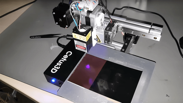
The printer in question is a Cetus3D, one of the newer generation of affordable machines. The printer has nice linear bearings but not a lot of other amenities, hence [Marco]’s desire to add a heated bed. But hiding beneath the covers was a suspicious transistor wired to a spare connector on the print head; a little sleuthing and a call to the factory revealed that the pin is intended for accessory use and can be controlled from G-code. With a few mods to the cheap UV laser module [Marco] had on hand, a printed holder for the laser, and a somewhat manual software toolchain, PCBs with 0.2-mm traces were soon being etched. The video below shows that the printer isn’t perfect for the job; despite the smooth linear bearings, the low mass of the printer results in vibration that shows up as wavy traces. But the results are more than acceptable, especially for $330.
This isn’t [Marco]’s first budget laser-etching rodeo. He recently tried the same thing using a cheap CNC laser engraver with similar results. That was a $200 dedicated engraver, this is a $300 3D printer with a $30 laser. It seems hard to lose at prices like these.
Continue reading “Entry-Level 3D Printer Becomes Budget PCB Machine”