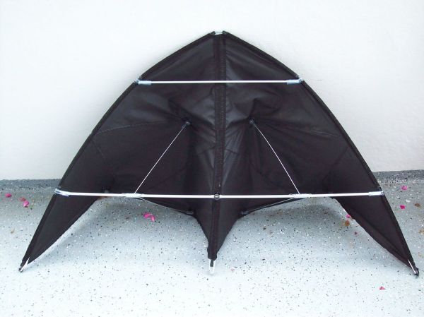
Word Clock: Tell The Time With Words

wordclock

[drj113]  posts his cool word clock. After seeing a similar clock on an industrial design website, he set out to make his own version. He made custom pcbs with the toner-etch method. The front is a solid piece of copper clad board and the light shines through the etched areas. It’s powered by a PIC microcontroller and uses approximately 120 ultra bright LEDs. [drj113] has all of the circuit board diagrams, silkscreens, etch negatives, and code on the intructable so you can build your own.

Repair A Malfunctioning LCD

When most people encounter dead pixels on an LCD text display, they figure that the display is dead and they decide to scrap it. However when the LCD display on one of [Joe]’s cordless phones started to show dead rows and columns of pixels, [Joe] decided that he could fix it. With only a pencil eraser, a hot air gun, and a screwdriver (for disassembly), [Joe] was able to fix his phone’s screen in just under 10 minutes. His process involves heating the glue holding the LCD’s ribbon cable to the phones PCB with a hot air gun and using a pencil eraser to reattach segments of the ribbon cable to the PCB. If anyone here has a problem similar to [Joe]’s, be sure to check out his detailed how-to complete with step-by-step pictures.

RGBike POV

rgbike_pov

[Hazard] wanted a full color POV display for his bike wheel. Adafruit’s SpokePOV is single color and Monkeylectric’s original version didn’t display images. He also balked at the cost and decided to manufacture his own version. It uses 16 RGB LEDs on a single layer board he manufactured himself. It’s an entirely through-hole design to make assembly easy. It uses a hall effect sensor to synchronize the image display. The two main components are an ATmega328p microcontroller, which should make it Arduino compatible, and a TLC5940 PWM LED driver. It’s a very well documented build and certainly a good looking effect.

[via adafruit]

Ferric Chloride Etching Chemistry

[ladyada] has republished an interesting snippet from the synthDIY mailing list. [David Dixon] discusses the actual chemistry behind ferric chloride based home circuit board etching. He concludes that ferric chloride is essentially a ‘one-shot’ oxidant. It can’t be regenerated and can be difficult to dispose of properly. The use of acidified copper chloride is a much better path and becomes more effective with each use, as long as you keep it aerated and top up the acidity from time to time. This etchant solution is actually the result of initially using hydrogen peroxide as an oxidant along with muriatic acid. You can see us using this solution in our etching how-to and while creating the board for our RGB lock. For more information on using hydrogen peroxide, check out [Adam Seychell]’s guide and this Instructable.

Aside: [ladyada] has added the receiver code to the Wattcher project page.

Resistive Ladder Volume Control

preamp

[jefffolly] published some straight forward plans for a passive volume control. It uses a resistive ladder built across the contacts of 12W rotary switches. Each resistor provides a 5dB difference, and he recommends using 0.1% tolerance resistors to maintain accuracy. The use of discrete resistors instead of volume pots means that the output is much more predictable. All of the RCA sockets were connected using oxygen-free copper wire.

Scratch Built RFID Tags

rfid

[nmarquardt] has put up an interesting instructable that covers building RFID tags. Most of them are constructed using adhesive copper tape on cardstock. The first version just has a cap and a low power LED to prove that the antenna is receiving power. The next iteration uses tilt switches so the tag is only active in certain orientations. The conclusion shows several different variations: different antenna lengths, conductive paint, light activated and more.