While most of us will never set foot in a fighter jet, some of us can still try to get as close as possible. One of the most eye-catching features of a fighter jet (at least from the pilot’s point-of-view) is the heads-up display, so that’s exactly what [Frank] decided to build into his car to give it that touch of fighter jet style.
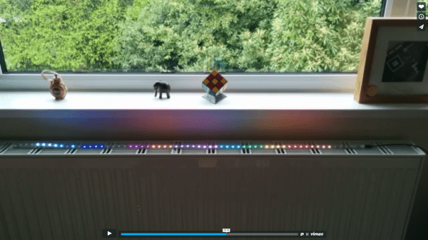
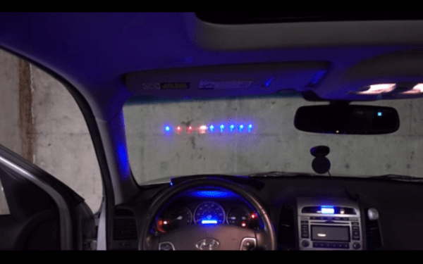
Heads-up displays use the small reflectivity of a transparent surface to work. In this case, [Frank] uses an LED strip placed on the dashboard to shine up into the windshield. A small amount of light is reflected back to the driver which is able to communicate vehicle statues without obscuring view of the road. [Frank]’s system is able to display information reported over the CAN bus, including voltage, engine RPM, and speed.
This display seems to account for all the issues we could think up. It automatically cycles through modes depending on driving style (revving the engine at a stoplight switches it to engine RPM mode, for example), the LEDs automatically dim at night to avoid blinding the driver, and it interfaces with the CAN bus which means the ability to display any other information in the future should be relatively straightforward. [Frank] does note some rough edges, though, namely with the power supply and the fact that there’s a large amount of data on the CAN bus that the Teensy microcontroller has a hard time sorting out.
That being said, the build is well polished and definitely adds a fighter jet quality to the car. And if [Frank] ever wants even more aviation cred for his ground transportation, he should be able to make use of a 747 controller for something on the dashboard, too.