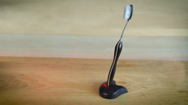
Most of us probably get by with a toothbrush costing a couple dollars at most, made of injection-moulded plastic for delicate, tender mouths. Maybe if you’re a real cleantooth, you have a fancy buzzy electric one. We’d wager few are machining their own bespoke toothbrushes from scratch, but if you want some inspiration, [W&M Levsha] is doing just that.
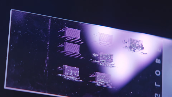
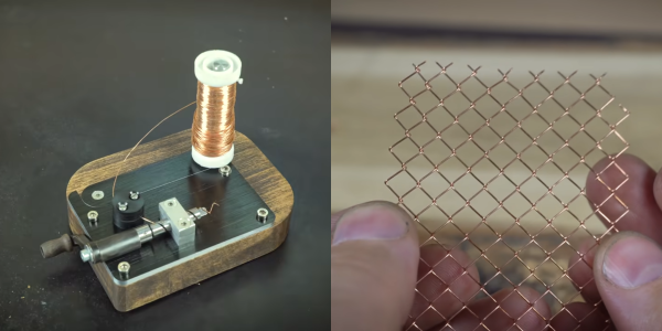
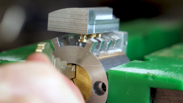
Much of the work will be familiar to die hard machining enthusiasts. There’s careful crafting of the wood handle, involving a stackup of multiple stained and varnished woods – in this case, hornbeam being the paler of the two, and amaranth providing that rich red color. The stem is a stylish stainless steel piece, elegantly bent to a tasteful curve. Finally, the assembly of the brush head alone is worth the watch. It’s custom made – with a steel backing plate and fishing wire bristles custom cut with an automated jig using stepper motors. We’re suspect fishing wire is not rated for dental use, but the nylon strands are at least in the ballpark of what regular toothbrushes use.
While we probably wouldn’t slide this one betwixt our lips without consulting a dental professional first, it’s a great video for learning about what it takes to make beautiful bespoke objects in the workshop. We’ve seen elegant work from [W&M Levsha] before, too – in the form of a delightfully eclectic cap gun lighter. Video after the break.
Continue reading “Making A Toothbrush From Scratch, Right Down To The Bristles”