Replace Your Calipers With A Microscope And Image Analysis

Getting a good measurement is a matter of using the right tool for the job. A tape measure and a caliper are both useful tools, but they’re hardly interchangeable for every task. Some jobs call for a hands-off, indirect way to measure small distances, which is where this image analysis measuring technique can come in handy.

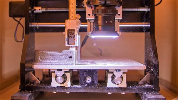
Although it appears [Saulius Lukse] purpose-built this rig, which consists of a microscopic lens on a digital camera mounted to the Z-axis of a small CNC machine, we suspect that anything capable of accurately and smoothly transitioning a camera vertically could be used. The idea is simple: the height of the camera over the object to be measured is increased in fine increments, with an image acquired in OpenCV at each stop. A Laplace transformation is performed to assess the sharpness of each image, which when plotted against the frame number shows peaks where the image is most in focus. If you know the distance the lens traveled between peaks, you can estimate the height of the object. [Salius] measured a coin using this technique and it was spot on compared to a caliper. We could see this method being useful for getting an accurate vertical profile of a more complex object.

From home-brew lidar to detecting lightning in video, [Saulius] has an interesting skill set at the intersection of optics and electronics. We’re looking forward to what he comes up with next.

Wireless SMD microscope ring light

Wireless Ring Light For SMD Microscope

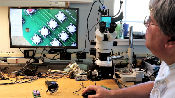
When [Felix Rusu], maker of the popular Moteino boards which started life as wireless Arduino compatibles, says he’s made a wireless ring light for his SMD microscope, we redirect our keystrokes to have a look. Of course, it’s a bit of wordplay on his part. What he’s done is made a new ring light which uses a battery instead of having annoying wires go to a wall wart. That’s important for someone who spends so much time hunched over the microscope. Oh, and he’s built the ring light on a rather nice looking SMD board.

The board offers a few power configurations. Normally he powers it from a 1650 mAh LiPo battery attached to the rear of his microscope. The battery can be charged using USB or through a DC jack for which there’s a place on the board, though he hasn’t soldered one on yet. In a pinch, he can instead power the light from the USB or the DC jack, but so far he’s getting over 6 hours on a single charge, good enough for an SMD session.

The video below shows his SMD board manufacturing process, from drawing up the board in Eagle, laser cutting holes for a stencil, pasting, populating the board, and doing the reflow, along with all sorts of tips along the way. Check it out, it makes for enjoyable viewing.

Here’s another microscope ring light with selectable lighting patterns for getting rid of those pesky shadows. What features would make your SMD sessions go a little easier?

Continue reading “Wireless Ring Light For SMD Microscope”

Motorized Stage Finesses The Microscopic World

No matter how fine your fine motor skills may be, it’s really hard to manipulate anything on the stage of a microscope with any kind of accuracy. One jitter or caffeine-induced tremor means the feature of interest on the sample you’re looking at shoots off out of the field of view, and getting back to where you were is a tedious matter of trial and error.

Mechanical help on the microscope stage is nice, and electromechanical help is even better, but a DIY fully motorized microscope stage with complete motion control is the way to go for the serious microscopist on a budget. Granted, not too many people are in [fabiorinaldus]’ position of having a swell microscope like the Olympus IX50, and those that do probably work for an outfit that can afford all the bells and whistles. But this home-brew stage ticks off all the boxes on design and execution. The slide is moved across the stage in two dimensions with small NEMA-8 steppers and microstepping controllers connected to two linear drives that are almost completely 3D-printed. The final resolution on the drives is an insane 0.000027344 mm. An Arduino lives in the custom-built control box and a control pad with joystick, buttons, and an OLED display allow the stage to return to set positions of interest. It’s really quite a build.

We’ve featured a lot of microscope hacks before, most of them concerning the reflective inspection scopes we all seem to covet for SMD work. But that doesn’t mean we haven’t shown love for optical scopes before, and electron microscopes have popped up a time or two as well.

Continue reading “Motorized Stage Finesses The Microscopic World”

Dark Field Microscopy On The Cheap With A PCB

It might seem like a paradox that you want a dark field to see things with an expensive microscope. As [IMSAI Guy] explains, a dark field microscope doesn’t make the subject dark. It makes the area surrounding the subject dark. After selling his expensive microscope, he found he missed having the capability, so he decided to make one cheaply. You can see how he did it in the video, below.

Dark field microscopy gives better contrast and resolution by discarding light that shines directly through or reflects directly from a sample. The only light you see is any that scatters. If you think about a normal microscope, you can imagine a cone of light coming from the top or the bottom. The tip of the cone hits the sample and then spreads back out into another cone of light. What hits your eye –well, actually, the eyepiece — is all the light from that cone. In a dark field instrument, the illumination cone is hollow — the light is just a ring. That means any light the sample doesn’t scatter gets blocked by a stop in the objective. When there is no sample, there’s no unblocked light, so you see a “dark field.”

Light that either refracts through the sample (from below) or bounces off a feature (from the top) will wind up in the hollow area that passes through the objective and you’ll see the image. It may surprise you that you may already have a piece of dark field technology on your desk. Optical computer mice that can work on glass surfaces use this same technique. If you want to see some examples and a diagram of how it all works, we did a post on a similar lower tech mod. There’s also Wikipedia.

The secret to doing this cheaply was to get a used dark field objective with a little rust on the barrel and then modify them with a custom PC board to create an LED ring light. This is different from the usual illuminator which shines a light through a patch stop to block the inner light. In this case, the light is made into a ring shape by virtue of the arrangement of the LEDs.

Continue reading “Dark Field Microscopy On The Cheap With A PCB”

Pimp My Scope

Most of us have heard some form of the adage, “You can buy cheaper, but you’ll never pay less.” It means that cheaper products ultimately do not stand up to the needs of their superior counterparts. Hackers love to prove this aphorism wrong by applying inexpensive upgrades to inexpensive tools to fill up a feature-rich tool bag. Take [The Thought Emporium] who has upgraded an entry-level microscope into one capable of polarized and dark-field microscopy. You can also see the video after the break.

Functionally, polarized images can reveal hidden features of things like striations in crystals or stress lines in hot glue threads. Dark-field microscopy is like replacing the normally glaring white background with a black background, and we here at Hackaday approve of that décor choice. Polarizing filters sheets are not expensive and installation can be quick, depending on your scope. Adding a dark-field filter could cost as much as a dime.

Like most mods, the greatest investment will be your time. That investment will pay back immediately by familiarizing you with your tools and their workings. In the long-run, you will have a tool with greater power.

Simple mods like the light source can be valuable, but upgrades are not limited to optical scopes, an electron microscope was brought back to life with Arduino

Continue reading “Pimp My Scope”

Impossibly Huge Depth Of Focus In Microscope Photographs

Sometimes, less is more. Sometimes, more is more. There is a type of person who believes that if enough photos of the same subject are taken, one of them will shine above the rest as a gleaming example of what is possible with a phone camera and a steady hand. Other people know how to frame a picture before hitting the shutter button. In some cases, the best method may be snapping a handful of photos to get one good one, not by chance, but by design.

[The Thought Emporium]’s video, also below the break, is about getting crisp pictures from a DSLR camera and a microscope using focus stacking, sometimes called image stacking. The premise is to take a series of photos that each have a different part of the subject in focus. In a microscope, this range will be microscopic but in a park, that could be several meters. When the images are combined, he uses Adobe products, the areas in focus are saved while the out-of-focus areas are discarded and the result is a single photo with an impossible depth of focus. We can’t help but remember those light-field cameras which didn’t rely on moving lenses to focus but took many photos, each at a different focal range.

[The Thought Emporium] has shown us his photography passion before, as well as his affinity for taking the cells out of plants and unusual cuts from the butcher and even taking a noble stab at beating lactose intolerance.

Continue reading “Impossibly Huge Depth Of Focus In Microscope Photographs”

Simple Mechanism Gives Support For SMT Assembly

With the fine work needed for surface-mount technology, most of the job entails overcoming the limits of the human body. Eyes more than a couple of decades old need help to see what’s going on, and fingers that are fine for manipulating relatively large objects need mechanical assistance to grasp tiny SMT components. But where it can really fall apart is when you get the shakes, those involuntary tiny muscle movements that we rarely notice in the real world, but wreak havoc as we try to place components on a PCB.

To fight the shakes, you can do one of two things: remove the human, or improve the human. Unable to justify a pick and place robot for the former, [Tom] opted to build a quick hand support for surface-mount work, and the results are impressive considering it’s built entirely of scrap. It’s just a three-piece arm with standard butt hinges for joints; mounted so the hinge pins are perpendicular to the work surface and fitted with a horizontal hand rest, it constrains movement to a plane above the PCB. A hole in the hand rest for a small vacuum tip allows [Tom] to pick up a part and place it on the board — he reports that the tackiness of the solder paste is enough to remove the SMD from the tip. The video below shows it in action with decent results, but we wonder if an acrylic hand rest might provide better visibility.

Not ready for your own pick and place? That’s understandable; not every shop needs that scale of production. But we think this is a great idea for making SMT approachable to a wider audience.

Continue reading “Simple Mechanism Gives Support For SMT Assembly”