Building A New RF Remote From Scratch

We’ve seen no shortage of projects that use the ESP8266 or ESP32 to add “smart” features to existing home appliances, often by pairing the microcontroller with a radio or IR transmitter. If your device has an existing remote, integrating it into a custom home automation system is often just a matter of getting a few cheap modular components and writing some simple code to glue it all together.

But what if the appliance you want to control doesn’t use a common frequency? That’s a question that [eigma] recently had to answer after finding the remote control for the bedroom ceiling fan was operating at a somewhat unusual 304 MHz. Something like the MAX1472 could probably have been tuned to this frequency, but the chip doesn’t seem to be available in a turn-key module as the popular 315 MHz transmitters are.

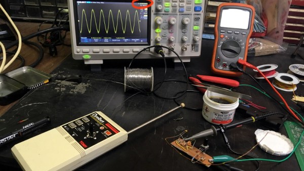
There were a few possible options, including using a software defined radio (SDR), but [eigma] didn’t want to spend a fortune on this project or wait months for parts to get shipped from overseas. The most straightforward solution was to design a custom transmitter tuned to the proper frequency using discrete components; something of a dark art to those of us who’ve been spoiled by the high availability of modular components.

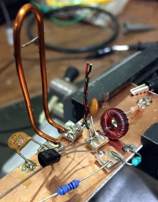
What follows is an fascinating look at the design, testing, and troubleshooting of a truly scratch-built transmitter. You won’t find any ICs here, the carrier signal is generated with just a transistor, some carefully measured pieces of wire, and a handful of passive components. By modulating the signal with an ESP32, [eigma] successfully makes the oddball ceiling fan an honorary member of the Internet of Things.

The write-up that [eigma] has done is an absolutely invaluable resource if you ever find yourself in need of rolling a bespoke transmitter. It easily ranks among some of the most informative radio reverse engineering work we’ve covered, and you’d be wise to file this one away for future reference. That said, most of the newer hardware you’re going to run into will probably be utilizing a widely-supported frequency like 433 MHz.

A Dangerous Demonstration Of The Power Of Radio

Terrestrial radio may be a dying medium, but there are still plenty of listeners out there. What would a commute to or from work be without a check of “Traffic on the Eights” to see if you need to alter your route, or an update of the scores from yesterday’s games? Getting that signal out to as many listeners as possible takes a lot of power, and this dangerous yet fascinating demo shows just how much power there is on some radio towers.

Coming to us by way of a reddit post, the short video clips show a crew working on a 15,000-Watt AM radio tower. They appear to be preparing to do tower maintenance, which means de-energizing the antenna. As the engineer explains, antennas for AM radio stations in the medium-wave band are generally the entire tower structure, as opposed to the towers for FM and TV stations, which generally just loft the antenna as high as possible above the landscape. The fun starts when the crew disconnects a jumper and an arc forms across the clamp and the antenna feed. The resulting ball of plasma acts like a speaker, letting us clearly hear the programming on the station. It’s like one of the plasma speakers we’ve seen before, albeit exceptionally more dangerous.

It’s an impressive display of the power coursing through broadcast towers, and a vivid reminder to not mess with them. Such warnings often go unheeded, sadly, with the young and foolish paying the price. There’s a reason they put fences up around radio towers, after all.

Continue reading “A Dangerous Demonstration Of The Power Of Radio”

Bitluni Brings All The ESP-32 Multimedia Hacks To Supercon

Of all the people I was looking forward to meeting at Supercon, aside from my Hackaday colleagues with whom I had worked for five years without ever meeting, was a fellow from Germany named Matthias Balwierz. The name might not ring a bell, but he’ll certainly be familiar to Hackaday readers as Bitluni, the sometimes goofy but always entertaining and enlightening face of “Bitluni’s Lab” on YouTube.

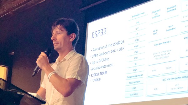
I’d been covering Bitluni’s many ESP32 hacks over the years, and had struck up a correspondence with him, swapping ideas and asking for advice on the many projects I start but somehow never finish. Luckily for us, Bitluni is far better on follow-through than I am, and he brought that breadth and depth of experience to the Design Lab stage for that venue’s last talk of the 2019 Superconference, before the party moved next door for the badge-hacking presentations.

Continue reading “Bitluni Brings All The ESP-32 Multimedia Hacks To Supercon”

Name That Unknown RF Signal With A Little FFT Magic

Time was once that the amateur radio bands were an aurally predictable place. Spinning the dial up and down the bands, one heard familiar sounds – the staccato of Morse, the [Donald Duck] of sideband voice transmissions, and the occasional flute-like warble of radioteletype signals. Now, the ham bands are full of exotic signals encoding all manner of digital signals, each one with a unique sound and unique demodulation needs. What’s a ham to do?

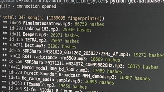
Help is on the way. [José Carlos Rueda] has made progress toward automatically classifying unknown signals by modifying a Shazam-like app. Shazam is a popular smartphone app that listens to a few seconds of a song, creates an audio fingerprint of it, and searches a massive database of songs for a match. [Rueda] used a homebrew version of the app to search a SQL-lite database of audio fingerprints populated not with a playlist of popular music, but with samples from every known signal type in the Signal Identification Wiki. The database contains hashes for an FFT of each sample, which can be easily searched. With a five to ten second sample of a signal, captured either live over a microphone or from a recording,  he is able to identify the signal automatically.

Whether it be the weird, dissonant wail of PSK-31 or the angry buzzing of PACTOR, the goings-on across the bands no longer have to remain a mystery. We really like the idea here, and wonder if it can be expanded upon to visually decode signals based on their waterfall signatures using TensorFlow. There are some waterfall examples in [Danie Conradie]’s excellent article on RF modulation that could get you started.

[via RTL-SDR.com]

RF Modulation: Crash Course For Hackers

When you’re looking to add some wireless functionality to a project, there are no shortage of options. You really don’t need to know much of the technical details to make use of the more well-documented modules, especially if you just need to get something working quickly. On the other hand, maybe you’ve gotten to the point where you want to know how these things actually work, or maybe you’re curious about that cheap RF module on AliExpress. Especially in the frequency bands below 1 GHz, you might find yourself interfacing with a module at really low level, where you might be tuning modulation parameters. The following overview should give you enough of an understanding about the basics of RF modulation to select the appropriate hardware for your next project.

Three of the most common digital modulation schemes you’ll see in specifications are Frequency Shift Keying (FSK), Amplitude Shift Keying (ASK), and LoRa (Long Range). To wrap my mechanically inclined brain around some concepts, I found that thinking of RF modulation in terms of pitches produced by a musical instrument made it more intuitive.

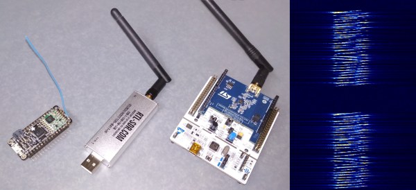
And lots of pretty graphs don’t hurt either. Signals from two different RF dev boards were captured and turned into waterfall and FFT plots using a $20 RTL-SDR dongle. Although not needed for wireless experimentation, the RTL-SDR is an extremely handy debugging tool, even to just check if a module is actually transmitting. Continue reading “RF Modulation: Crash Course For Hackers”

Universal music translation network

Hiding Data In Music Might Be The Key To Ditching Coffee Shop WiFi Passwords

In a move guaranteed to send audiophiles recoiling back into their sonically pristine caves, two doctoral students at ETH Zurich have come up with an interesting way to embed information into music. What sounds crazy about this is that they’re hiding data firmly in the audible spectrum from 9.8 kHz to 10 kHz. The question is, does it actually sound crazy? Not to our ears, playback remains surprisingly ok.

You can listen to a clip with and without the data on ETH’s site and see for yourself. As a brief example, here’s twelve seconds of the audio presenting two versions of the same clip. The first riff has no data, and the second riff has the encoded data.

You can probably convince yourself that there’s a difference, but it’s negligible. Even if we use a janky bandpass filter over the 8 kHz -10 kHz range to make the differences stand out, it’s not easy to differentiate what you’re hearing:

After many years of performing live music and dabbling in the recording studio, I’d describe the data-encoded clip as having a tinny feedback or a weird reverb effect. However, you wouldn’t notice this in a track playing on the grocery store’s speaker. Continue reading “Hiding Data In Music Might Be The Key To Ditching Coffee Shop WiFi Passwords”

Driving A 16×2 LCD With Voltage Modulation

The basic 16×2 LCD is an extremely popular component that we’ve seen used in more projects than we could possibly count. Part of that is because modern microcontrollers make it so easy to work with; if you’ve got an I2C variant of the display, it only takes four wires to drive it. That puts printing a line of text on one of these LCDs a step or two above blinking an LED on a digital pin on the hierarchy of beginner’s electronics projects.

What’s that? Even four wires is too many? In that case, you might be interested in this hack from [Vinod] which shows how you can drive the classic 16×2 with data and power on the same pair of wires. You’ll still need a microcontroller “backpack” for the LCD to interpret the modulated voltage, but if you’ve got an application for a simple remote display, this is definitely worth checking out.

The basic idea is to “blink” the 5 V line so quick that a capacitor on the LCD side can float the electronics over the dips in voltage. As long as one of the pins of the microcontroller is connected to the 5 V line before the capacitor, it will be able to pick up when the line goes low. With a high enough data rate and a large enough capacitor as a buffer, you’re well on the way to encoding your data to be displayed.

For the transmitting side, [Vinod] is using a Python script on his computer that’s sending out the text for the LCD over a standard USB to UART converter. That’s fed into a small circuit put together on a scrap of perfboard that triggers a MOSFET off of the UART TX line.

We actually covered the theory behind this technique years ago, but it’s always interesting to see somebody put together a real-world example. There might not be too many practical uses for this trick in the era of dirt-cheap microcontrollers bristling with I/O, but it might make a fun gag at your hackerspace.

Continue reading “Driving A 16×2 LCD With Voltage Modulation”