5 Kilowatts In A 3D Printed Jet Boat

Radio control projects used to be made of materials such as metal or wood, and involve lots of hand crafted parts. That’s still one way to go about things, but 3D printing has become a popular tool in recent years. [RCLifeOn] has been working on a 3D printed jet boat, which recently got a serious power upgrade.

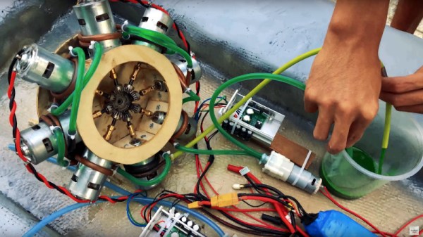
The boat in question received a 5000W brushless motor – significant power for a vehicle weighing less than 2kg. Powered by a 12S lithium pack, and outfitted with a water jacket for cooling, it drives the boat through an off-the-shelf turbine after initial attempts to DIY the drivetrain were unsuccessful.

The biggest problem in the project came from coupling the motor to the turbine. A 3D printed coupler was unable to hold up to the strain, while attempts to make a metal part failed due to the lack of a lathe. Eventually the solution was found by daisy chaining two off-the-shelf parts together.

The boat proved itself ably on the water, with the large motor proving more than capable of shifting the boat at a strong clip. It’s an excellent shakedown for the parts that will eventually find themselves in a powered surfboard build. We’ve seen [RCLifeOn]’s work before, too, like these stylish 3D printed sneakers. Video after the break.

Continue reading “5 Kilowatts In A 3D Printed Jet Boat”

Axiom, A 100+kW Motor Controller For Making Big Motors Move

We’ve seen a lot of motor driver boards for robots and the odd electric skateboard. What we haven’t see a lot of is one big enough to drop into an electric vehicle. 

The Axiom motor controller was a winner of the bootstrap contest and is a Finalist in the 2019 Hackaday Prize. The driver aims to deliver 300A continuous at 400V all day long. Which is a very impressive amount of power from a board that appears to be quite compact.

The brains of the device is an ice40 FPGA from Lattice running software based on the VESC Project. Its open source roots will certainly allow for some interesting hacks and an increasingly stable platform over time. Not to mention the existing software tools will aid in the sometimes cumbersome motor-driver tuning process.

The board designs are available, but we agree with the team that the complexity of assembly is likely going to be high (along with the price). The amount of research and skill going into this complicated kit is a bit mind-boggling, but we hope it will really enable some cool hacks, from cars, to ATVs, and maybe even an electric flyer.

A (Mostly) 3D Printed Servo/Gear Reduction

This servo/gear reduction was assembled with almost all 3D-printed parts. Apart from a brushed 36 V DC-motor, a stainless steel shaft, and screws for holding the servo together, the only other non-printed part is the BTS7960B motor driver.

Some interesting stats about the plastic servo – its stall torque is about 55 kg/cm, reaching a peak current draw of 18 A when using a 6s LiPo battery outputting 22-24 V. The shaft rotates using two 20 mm holes and lubrication. (Ball bearings were originally in the design, but they didn’t arrive on time for the assembly.)

The holes of the gears are 6.2 mm in diameter in order to fit around the shaft, although some care is taken to sand or fill the opening depending on the quality of the 3D print.

This isn’t [Brian Brocken]’s only attempt at 3D-printing gears. He’s also built several crawling robots, a turntable, and a wind up car made entirely from acrylic. The .stl files for the project are all available online for anyone looking to make their own 3D-printed servo gears.

Continue reading “A (Mostly) 3D Printed Servo/Gear Reduction”

Stunning 4-Cylinder Solenoid Motor Should Be A Hit With Subaru Fans

As far as electric propulsion is concerned, the vast majority of applications make use of some kind of rotational motor. Be it induction, universal, brushed or brushless, these are the most efficient ways we have to do mechanical work with electricity. There are other, arcane methods, though – ones which [Maker B] explores with this 4-cylinder solenoid engine.

The principle of the solenoid engine is simple. Cylinders are wound with coils to act as solenoids, with the piston acting as the armature. When the solenoid is energised, it pulls the piston into the cylinder. The solenoid is then de-energised, and the piston can return to its initial position. The piston is coupled to a crankshaft via a connecting rod, and a flywheel is used to help the motor run continually. These are also known as reciprocating electric motors.

[Maker B]’s build is a 4-cylinder design in a boxer configuration. Produced with basic hand-operated machine tools, the build process is one to watch. Aluminium and brass are carefully crafted into the various components of the motor, and parts are delicately assembled with small fasteners and plenty of retaining compound. Solenoid timing is via a series of microswitches, installed neatly in the base of the motor and actuated by the crankshaft.

While solenoid motors are inefficient, they’re quite something to watch in action. This one is no exception, with the motor spinning up to 1100 rpm when running at 7.2 volts. We’d love to see some data on the power output and efficiency too. It’s possible to build solenoid motors in different configurations, too – this radial build is particularly fun. Video after the break.

Continue reading “Stunning 4-Cylinder Solenoid Motor Should Be A Hit With Subaru Fans”

(Mis)use This Part To Attach 3D Printed Stuff To A Shaft

Interfacing a shaft to a 3D printed gear doesn’t have to be tricky. [Tlalexander] demonstrated a solution that uses one half of a spider coupling (or jaw coupling) to create an effective modular attachment. The picture above (and this older link) shows everything you need to know: the bottom of the coupling is mounted to the shaft, and a corresponding opening is modeled into the the 3D printed part. Slide the two together, and the result is a far sturdier solution than trying to mate a 3D printed gear directly to a motor shaft with a friction fit or a screw. This solution isn’t necessarily limited to attaching gears either, any suitable 3D printed part could be interfaced to a shaft in this way.

These couplings are readily available, and fortunately for hobbyists, come in sizes specifically designed for common stepper motors like NEMA 17 and NEMA 23. Ironically, these couplings are often used when building custom 3D printers for those same reasons. With this method interfacing anything at all to a motor shaft becomes mostly a matter of modeling a matching hole out of the part to be 3D printed. One coupling even provides two such attachments, since only one of the two sides is used.

The image up top is from [Tlalexander]’s Rover image gallery, which contains a ton of fantastic pictures of the work that went into the gearboxes, a major part of the Rover’s design that we’ve seen in the past.

Spin Me Right Round, Baby: Generator Building Experiments For Mere Mortals

How many of you plan to build a wind-powered generator in the next year? Okay, both of you can put your hands down. Even if you don’t want to wind your coils manually, learning about the principles in an electric generator might spark your interest. There is a lot of math to engineering a commercial model, but if we approach a simple version by looking at the components one at a time, it’s much easier to understand.

For this adventure, [K&J Magnetics] start by dissect a commercial generator. They picked a simple version that might serve a campsite well, so there is no transmission or blade angle apparatus to complicate things. It’s the parts you’d expect, a rotor and a stator, one with permanent magnets and the other with coils of wire.

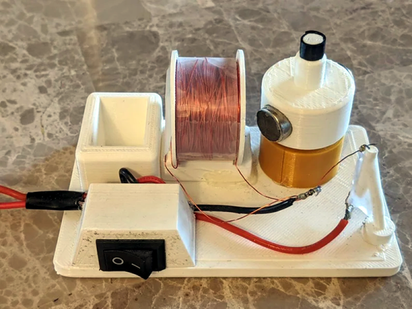
The fun of this project is copying the components found in the commercial hardware and varying the windings and coil count to see how it affects performance. If you have ever wound magnet wire around a nail to make an electromagnet, you know it is tedious work so check out their 3D printed coil holder with an embedded magnet to trigger a winding count and a socket to fit on a sewing machine bobbin winder. If you are going to make a bunch of coils, this is going to save headaches and wrist tendons.

They use an iterative process to demonstrate the effect of multiple coils on a generator. The first test run uses just three coils but doesn’t generate much power at all, even when spun by an electric drill. Six windings do better, but a dozen finally does the trick, even when turning the generator by hand. We don’t know about their use of cheap silicone diodes though, that seems like unintentional hobbling, but we digress.

Making turbine blades doesn’t have to be a sore chore either, and PVC may be the ticket there, you may also consider the vertical axis wind turbine which is safer at patio level. Now, you folks building generators, remember to tip us off!

Continue reading “Spin Me Right Round, Baby: Generator Building Experiments For Mere Mortals”

Deducing Stepper Motor Wiring

There are a lot of fun projects you can do with stepper motors salvaged from old printers or disk drives. However, it isn’t always clear how to connect to some strange motor with no markings or schematics. [Corvetteguy50] has a video showing his trick for working out the connections easily, and you can see it below.

The basic idea is simple. Using a special jig, he connects an LED across two random pins and spins the motor. If the LED lights, you’ve found a coil. You just don’t know which coil, yet. You can also short two wires and note when you feel resistance when you spin the shaft.

Continue reading “Deducing Stepper Motor Wiring”