That headline sounds suspect, but it is the most succinct way to explain why the Roland TR-808 drum machine has a very distinct, and difficult to replicate noise circuit. The drum machine was borne of a hack. As the Secret Life of Synthesizers explains, it was a rejected part picked up and characterized by Roland which delivers this unique auditory thumbprint.
Pictured above is the 2SC828-R, and you can still get this part. But it won’t function the same as the parts found in the original 808. The little dab of paint on the top of the transistor indicates that it was a very special subset of those rejected parts (the 2SC828-RNZ). A big batch of rejects were sold to Roland back in the 1970’s — which they then thinned out in a mysterious testing process. What was left went into the noise circuit that gave the 808 its magical sizzle. When the parts ran out, production ended as newer processes didn’t produce the same superbly flawed parts.
This is an incredible story that was highlighted in 808, a documentary premiered at SXSW back in 2015. The film is currently streaming on Amazon Prime (and to rent everywhere else) and is certainly worth your time just to grasp how seminal this drum machine has been in hip hop and several other music genres.
For modern product developers, betting your production on a batch of reject parts is just batty. But it was a very different time with a lot fewer components on the market. What worked, worked. You do have to wonder how you stumble upon the correct trait in an obscure batch of reject parts? Looks like we’ll be adding Ikutar Kakehashi’s bookI Believe in Music: Life Experiences and Thoughts on the Future of Electronic Music by the Founder of the Roland Corporation to our reading list.
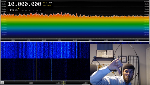
[K5ACL], aka [SignalSearch], recently brought his active receive loop antenna in off the roof to give it a checkup and perform any necessary maintenance. While it was in the shack, he took the opportunity to discuss how well it would perform indoors. The verdict? Not ideal. He’d mount it 50 feet away from the house if the HOA would let him.
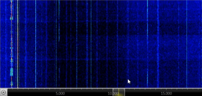
Houses, and subsequently most ham shacks, are filled with noise sources that interfere badly with HF. So after spending a minute or so listening on an SDR, [K5ACL] demonstrates another use for this type of tightly-tuned antenna—as a noise detector.
The main culprit in [K5ACL]’s house is the ceiling light that’s right there in the shack. You can see the noise striping the waterfall as he turns it on and off. But the noise from the light is small potatoes compared to some other common household items, like those power line adapters that turn house wiring into networking cable. Those produce so much noise that even an active loop is really no match. Stay tuned after the break to watch [K5ACL] work the bands through the noise.
Loop antennas are great if you’re stuck in an apartment building or a congested city. They’re easy enough to make, whether you want a portable loop or a permanent installation.
Your device starts with a speaker and a membrane. On this membrane will sit a handful of small, marble-size copper balls. An audio source feeds the speaker and causes the balls to bounce to and fro. If a ball bounces high enough, it will gain the opportunity to travel down one of seven copper tubes. Optical sensors in each of the tubes detect the ball and feed data to an Ardunio Mega. When the ball reaches the end of the tube, a robotic hand will take the ball and put it back on the speaker membrane. The magic happens when we write an algorithm such that the audio output for the speaker is a function of how many balls fall down the pipes.
The above is a rough description of [::vtol::]’s art piece: kinetic random number generator. We’re pretty sure that there are easier ways to get some non-determinstic bits, but there may be none more fun to watch.
Marketing guys love bigger numbers. Bigger is better, right? After all, Subway called it a “footlong” not an 11-incher. So when it comes to analog to digital (A/D) conversion, more bits are better, right? Well, that depends. It is easy to understand that an A/D will have a low and high measurement and the low will be zero counts and the high will result in the maximum count for the number of bits. That is, an 8-bit device will top out at 255, a 10-bit at 1023, and so on.
The question is: are those bits meaningful? The answer depends on a few factors. Like most components we deal with, our ideal model isn’t reality, but maybe it is close enough.
Cheap DC-DC converters have been a boon on the hobbyist bench for a while now, but they can wreak havoc with sensitive circuits if you’re not careful. The problem: noise generated by the switch-mode supply buried within them. Is there anything you can do about the noise?
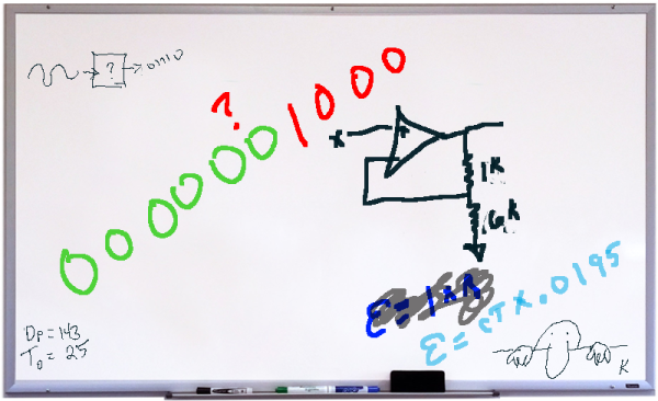
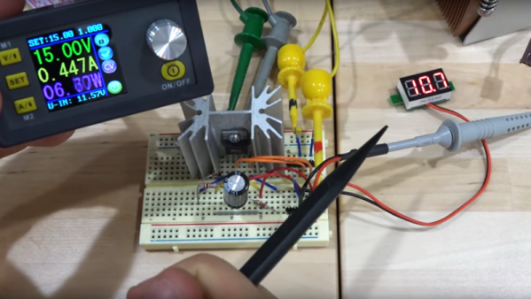
As it turns out, yes there is, and [Shahriar] at The Signal Path walks us through a basic circuit to reduce noise from DC-DC converters. The module under the knife is a popular buck-boost converter with a wide input range, 0-32 VDC output at up to 5 amps, and a fancy controller with an LCD display. But putting the stock $32 supply on a scope reveals tons of harmonics across a 1 MHz band and overall ripple of about 66 mV. But a simple voltage follower built from a power op-amp and a Zener diode does a great job of reducing the spikes and halving the ripple. The circuit is just a prototype and is meant more as a proof of principle and launching point for further development, and as such it’s far from perfect. The main downside is the four-volt offset from the input voltage; there’s also a broad smear of noise at the high end of the spectrum that persists even with the circuit in place. Centered around 900 MHz as it is, we suspect a cell signal of some sort is getting in. 900 kHz.
If you haven’t checked out the videos at The Signal Path, you really should. [Shahriar] really has a knack for explaining advanced topics in RF engineering, and has a bench to die for. We’ve covered quite a few of his projects before, from salvaging a $2700 spectrum analyzer to multiplexing fiber optic transmissions.
Like any Moore’s Law-inspired race, the megapixel race in digital cameras in the late 1990s and into the 2000s was a harsh battleground for every manufacturer. With the development of the smartphone, it became a war on two fronts, with Samsung eventually cramming twenty megapixels into a handheld. Although no clear winner of consumer-grade cameras was ever announced (and Samsung ended up reducing their flagship phone’s cameras to sixteen megapixels for reasons we’ll discuss) it seems as though this race is over, fizzling out into a void where even marketing and advertising groups don’t readily venture. What happened?
The Technology
A brief overview of Moore’s Law predicts that transistor density on a given computer chip should double about every two years. A digital camera’s sensor is remarkably similar, using the same silicon to form charge-coupled devices or CMOS sensors (the same CMOS technology used in some RAM and other digital logic technology) to detect photons that hit it. It’s not too far of a leap to realize how Moore’s Law would apply to the number of photo detectors on a digital camera’s image sensor. Like transistor density, however, there’s also a limit to how many photo detectors will fit in a given area before undesirable effects start to appear.
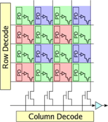
Image sensors have come a long way since video camera tubes. In the ’70s, the charge-coupled device (CCD) replaced the cathode ray tube as the dominant video capturing technology. A CCD works by arranging capacitors into an array and biasing them with a small voltage. When a photon hits one of the capacitors, it is converted into an electrical charge which can then be stored as digital information. While there are still specialty CCD sensors for some niche applications, most image sensors are now of the CMOS variety. CMOS uses photodiodes, rather than capacitors, along with a few other transistors for every pixel. CMOS sensors perform better than CCD sensors because each pixel has an amplifier which results in more accurate capturing of data. They are also faster, scale more readily, use fewer components in general, and use less power than a comparably sized CCD. Despite all of these advantages, however, there are still many limitations to modern sensors when more and more of them get packed onto a single piece of silicon.
While transistor density tends to be limited by quantum effects, image sensor density is limited by what is effectively a “noisy” picture. Noise can be introduced in an image as a result of thermal fluctuations within the material, so if the voltage threshold for a single pixel is so low that it falsely registers a photon when it shouldn’t, the image quality will be greatly reduced. This is more noticeable in CCD sensors (one effect is called “blooming“) but similar defects can happen in CMOS sensors as well. There are a few ways to solve these problems, though.
First, the voltage threshold can be raised so that random thermal fluctuations don’t rise above the threshold to trigger the pixels. In a DSLR, this typically means changing the ISO setting of a camera, where a lower ISO setting means more light is required to trigger a pixel, but that random fluctuations are less likely to happen. From a camera designer’s point-of-view, however, a higher voltage generally implies greater power consumption and some speed considerations, so there are some tradeoffs to make in this area.
Another reason that thermal fluctuations cause noise in image sensors is that the pixels themselves are so close together that they influence their neighbors. The answer here seems obvious: simply increase the area of the sensor, make the pixels of the sensor bigger, or both. This is a good solution if you have unlimited area, but in something like a cell phone this isn’t practical. This gets to the core of the reason that most modern cell phones seem to be practically limited somewhere in the sixteen-to-twenty megapixel range. If the pixels are made too small to increase megapixel count, the noise will start to ruin the images. If the pixels are too big, the picture will have a low resolution.
There are some non-technological ways of increasing megapixel count for an image as well. For example, a panoramic image will have a megapixel count much higher than that of the camera that took the picture simply because each part of the panorama has the full mexapixel count. It’s also possible to reduce noise in a single frame of any picture by using lenses that collect more light (lenses with a lower f-number) which allows the photographer to use a lower ISO setting to reduce the camera’s sensitivity.
Gigapixels!
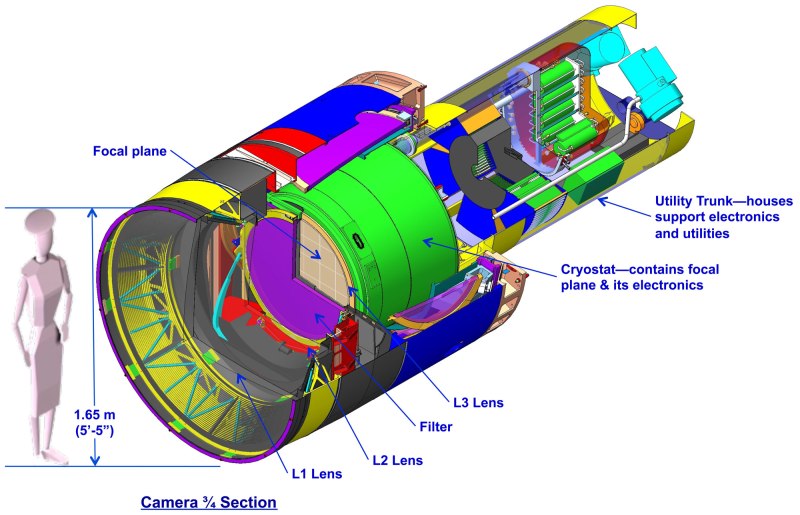
Of course, if you have unlimited area you can make image sensors of virtually any size. There are some extremely large, expensive cameras called gigapixel cameras that can take pictures of unimaginable detail. Their size and cost is a limiting factor for consumer devices, though, and as such are generally used for specialty purposes only. The largest image sensor ever built has a surface of almost five square meters and is the size of a car. The camera will be put to use in 2019 in the Large Synoptic Survey Telescope in South America where it will capture images of the night sky with its 8.4 meter primary mirror. If this was part of the megapixel race in consumer goods, it would certainly be the winner.
With all of this being said, it becomes obvious that there are many more considerations in a digital camera than just the megapixel count. With so many facets of a camera such as physical sensor size, lenses, camera settings, post-processing capabilities, filters, etc., the megapixel number was essentially an easy way for marketers to advertise the claimed superiority of their products until the practical limits of image sensors was reached. Beyond a certain limit, more megapixels doesn’t automatically translate into a better picture. As already mentioned, however, the megapixel count can be important, but there are so many ways to make up for a lower megapixel count if you have to. For example, images with high dynamic range are becoming the norm even in cell phones, which also helps eliminate the need for a flash. Whatever you decide, though, if you want to start taking great pictures don’t worry about specs; just go out and take some photographs!
(Title image: VISTA gigapixel mosaic of the central parts of the Milky Way, produced by European Southern Observatory (ESO) and released under Creative Commons Attribution 4.0 International License. This is a scaled version of the original 108,500 x 81,500, 9-gigapixel image.)
The police force in Evanston, Illinois had a problem on their hands. A mystery transmitter was blocking legal use of radio devices, car key fobs, cellphones, and other transmitters in an area of their city, and since it was also blocking 911 calls they decided to investigate it. Their first call for help went to the FCC who weren’t much use, telling them to talk to the manufacturers of the devices affected.
Eventually they approached the ARRL, the USA’s national amateur radio organisation, who sent along [Kermit Carlson, W9XA] to investigate. He fairly quickly identified the frequencies with the strongest interference and the likely spot from which it originated, and after some investigation it was traced to a recently replaced neon sign power supply. Surprisingly the supply was not replaced with a fault-free unit, its owner merely agreeing to turn it off should any further interference be reported.
The ARRL are highlighting this otherwise fairly unremarkable case to draw attention to the problem of devices appearing on the market with little or no pretence of electromagnetic compatibility compliance. In particular they are critical of the FCC’s lacklustre enforcement response in cases like this one. It’s a significant problem worldwide as huge numbers of very cheap switch-mode mains power supplies have replaced transformers in mains power applications, and in any center of population its effects can be readily seen with an HF radio in the form of a significantly raised RF noise floor. Though we have reported before on the FCC’s investigation of the noise floor problem we’d be inclined to agree with the ARRL that it is effective enforcement of EMC regulations that is key to the solution.
City of Evanston police vehicle picture, [Inventorchris] (CC BY-NC 2.0) via Flickr.