The best equipment won’t help you if you don’t have it with you in the moment you need it. Knowledge, experience, and a thick skin may help you out there in the mud of the hardware battlegrounds, but they can’t replace a multimeter, an oscilloscope, a logic analyzer, a serial console or a WiFi access point. [Arcadia Labs] has taken on the challenge of combining most of these functions into a single device, developing the Hacker’s equivalent of a Swiss Army Knife: The ESP Swiss Knife.
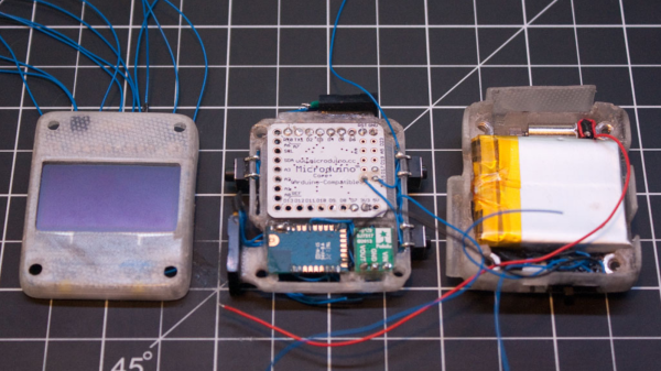
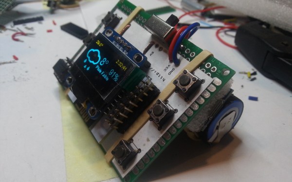
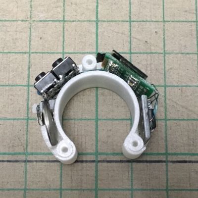
 Just like a Swiss Army Knife is first and foremost a knife, the EPS Swiss Knife is first and foremost an ESP8266. That means it is already a great platform for any kind of project, and [Arcadia Labs] supercharged the plain ESP-12E module by adding a couple of useful features commonly used in many projects. There’s an OLED display, four pushbuttons, a temperature sensor, and a Li-Ion cell with a charging module to power the device on the go. A universal “utility socket” breaks out the ESP8266’s leftover GPIOs and the supply voltage for attaching further peripherals.
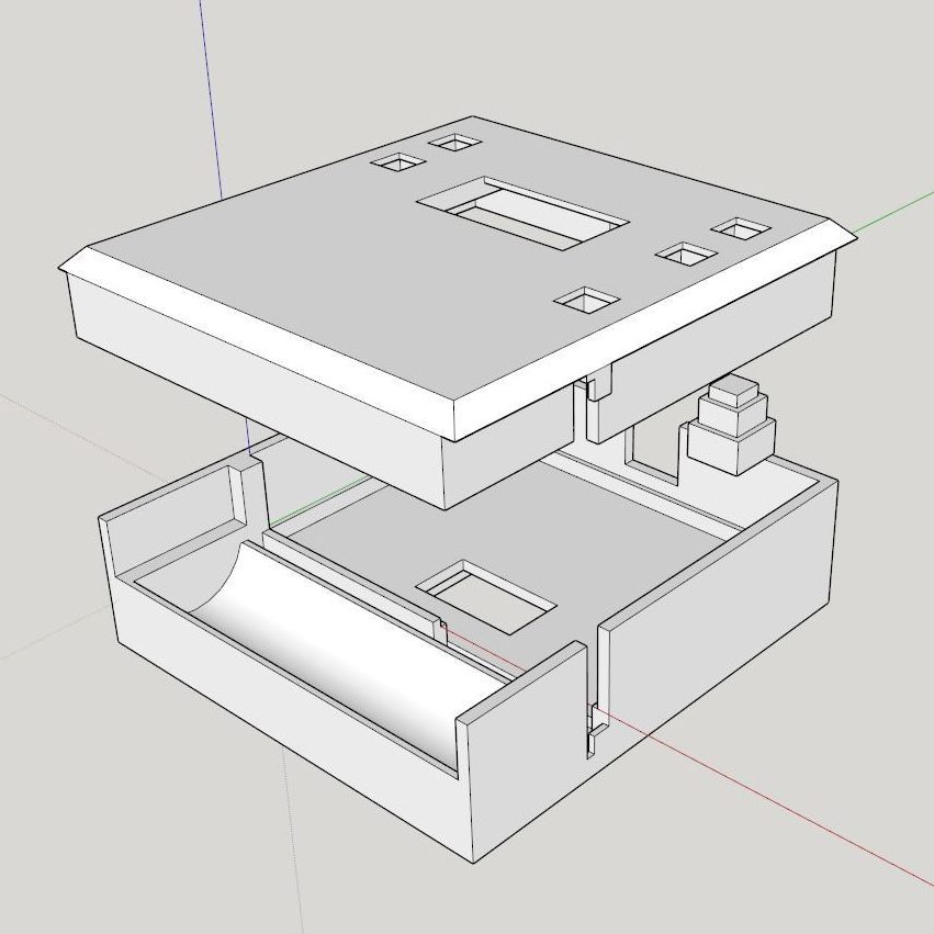
With the hardware up and running, [Arcadia Labs] went on with building a couple of applications to provide the functionality that would make the device earn its name. Among them is a basic oscilloscope, a digital NTP based clock, a thermometer, a WiFi tester, a weather station and a 3D printer status monitor. More applications are planned, such as a chronometer, a timer, a DSLR intervalometer and more. A protective 3D printable enclosure is also in the works. [Arcadia Labs] has been joining the Hackaday Prize 2014 and 2015 before and we’re glad to see another great build coming into existence!


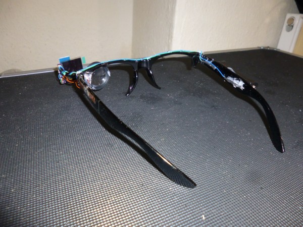
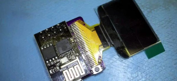
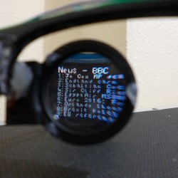 For his project, [Harris Shallcross] used a small 0.95″ diagonal 96×64 color OLED as the display. The lens is from a knockoff Google Cardboard headset, and is held in a 3D printed piece that slides along a wire rail to adjust focus. The display uses a custom font and is driven by an STM32 microcontroller on a small custom PCB, with an HM11 BLE module to receive data wirelessly. Power is provided by a rechargeable lithium-ion battery with a boost converter. An Android app handles sending small packets of data over Bluetooth for display. The prototype software handles display of time and date, calendar, BBC news feed, or weather information.
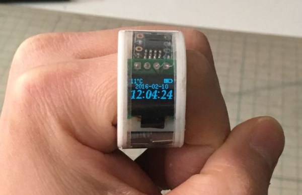
 The current iteration is complete and builds upon
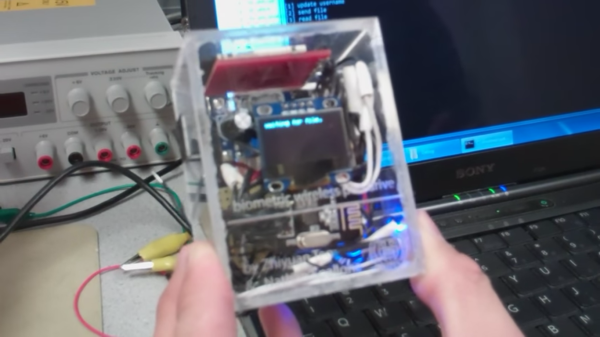
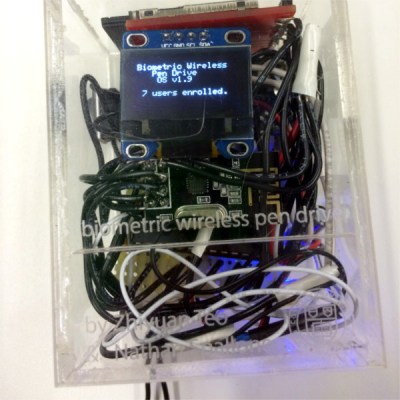 Their solution can be used by up to 20 different people who each get a slice of an SD card in the storage unit There are two physical pieces, a base station and the wireless storage unit itself. The base station connects to the host PC over USB and contains an Arduino for serial pass-through and an nRF24L01+ module for communicating with the storage side. The storage drive’s components are crammed inside a clear plastic box. This not only looks cool, it negates the need for cutting out ports to mount the fingerprint sensor and the OLED. The sensor reads the user’s credentials through the box, and the authentication status is displayed on an OLED. Files are transferred to and from the SD card over a second nRF24L01+ through the requisite PIC32.