No More Floppy Drives For This Agilent Scope

When [kiwih] picked up an Agilent 54621A scope, he was amused that it had a floppy disk. At one time, it was high-tech to use a disk to transfer scope data to your computer. Today, not so much. However, on the back was a serial port. Surely it was possible to read data from there. It is, and what results is a nice walkthrough of finding the port’s info and interfacing with it using Python.

Normally, you’d use the included BenchLinkXL software to grab data from the port, but that software is so old it would not run under Windows 10 or Wine. Searching didn’t turn up much on the serial port, but it did locate a manual for a similar Agilent scope. That manual wasn’t too helpful since it assumed you were connecting via a LAN or USB. However, it did make reference to an older model that was also similar and that was the key to finding a manual that did explain the serial port protocol.

The command set looks suspiciously like SCPI — Standard Commands for Programmable Instruments — which is a layer on top of the GPIB protocol. Many scopes speak that language, so that’s not surprising. That also means if you are in the mood to communicate with an SCPI scope, you might find the code useful, even if you don’t use a serial port or have this exact Agilent model.

SCPI has a lot of uses. For example, try talking to your scope. The cheap Rigol and similar scopes usually have SCPI and you can control and read them using the same kind of techniques.

Open-Source 2 GHz Oscilloscope Probe

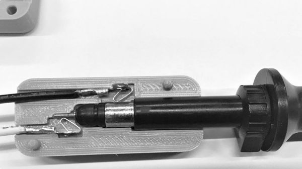
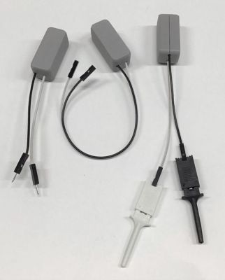
If you do any work with high-speed signals, you quickly realize that probing is an art unto itself. Just having a fast oscilloscope isn’t enough; you’ve got to have probes fast enough to handle the signals you want to see. In this realm, just any old probe won’t do: the input capacitance of the classic RC probe you so often see on low-bandwidth scopes starts to severely load down a circuit well below 1 GHz. That’s why we were really pleased to see [Andrew Zonenberg’s] new open-source design for a 2 GHz resistive probe hit Kickstarter.

The design of this new probe looks deceptively simple. Known as a Z0-probe, transmission-line probe, or resistive probe, the circuit works as a voltage divider, created from the 50-Ohm input impedance of a high-speed oscilloscope input and an external resistor, to reduce loading on the circuit-under-test. In this case, the input resistance has been chosen to be 500 Ohms, yielding a 10x probe. In theory, building such a probe is as simple as soldering a resistor to the end of a piece of coaxial cable. You can do exactly that, but in practice, optimizing a design is much more complex. As you can see in the schematic, just choosing a resistor of the right value doesn’t cut it at these frequencies. Even the tiny 0402-size resistors have parasitic capacitance and inductance that affect the response, and choosing a combination of parts that add to the correct resistance but reduce the overall capacitive loading makes a huge difference.

2 GHz Passive Probe Schematic

Don’t be fooled: the relatively simple schematic belies the complexity of such a design. At these speeds, the PCB layout is just as much of a component as the resistors themselves, and getting the transmission-line and especially the SMA footprint launch correct is no easy task. Using a combination of modeling with the Sonnet EM simulator and empirical testing, [Andrew] has ended up with a design that’s flat (+/- 1 dB) out to 1.98 GHz, with a 10-90% rise time of 161 ps. That’s a fast probe.

The probe comes in a few options, from fully assembled with traceable specs to a DIY solder-it-yourself version. You probably know which of these options you need.

We really like to see this kind of knowledge and thoroughness go into a project, and we’d love to see the Kickstarter project reach its goals, but perhaps the best part is that the design is permissively open-source licensed. This is a case where having the board layout open-sourced is key; the schematic tells you maybe half of what’s really going on in the circuit, and getting the PCB right yourself can be a long and frustrating exercise. So, have a look at the project, and if you haven’t got probes suitable for your fastest scopes, build one, or better yet, support the development of this exciting design.

We’ve seen [Andrew’s] oscilloscope work before, like glscopeclient, his remote oscilloscope utility program.

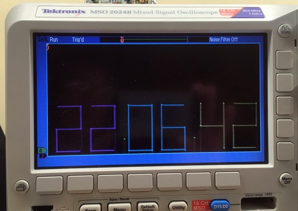
Scopetrex Is A Game Console… For Your Oscilloscope!

You’ve always wanted a game console at your bench, but maybe you haven’t had space for a monitor or TV set? Wouldn’t it be useful if the screen you do have on your bench could also play games? [Tube Time] has fixed this problem, with Scopetrex, a vector graphic console for your oscilloscope. In fact, it’s better than just a console, because it’s a clone of the legendary Vectrex, the vector-based console with built-in CRT screen from the 1980s.

The board itself is a slightly enhanced version of the original, offering not extra functionality but the ability to substitute some of the parts for more easily found equivalents. It gives full control over display size and brightness, can use the cheaper 6809E processor and AY-3-9810 sound chip if necessary, and only needs a single 5 volt supply. There’s also a custom controller board, which is handly Vectrex-compatible. All you will need to play Vectrex games on your ‘scope once you’ve built this board, are a copy of the Vectrex ROM, and some games.

The Vectrex holds an enduring fascination for our community, and has appeared here many times. Particularly memorable is a CRT replacement, and then of course there’s the never-released mini Vectrex prototype.

Thanks [Justin List] for the tip.

Fixing An Agilent Oscilloscope Power Supply

We should all be so lucky as [Salvaged circuitry], who scored a cheap Agilent oscilloscope from an online auction. Of course, its low price had a reason behind it, the ‘scope didn’t work. At fault was its power supply, the repair of which was documented in the video below.

These ‘scopes have relatively straightforward 12 V power supplies, extremely similar to off-the-shelf parts. The video is an interesting primer in switch-mode power supply repair, as the obvious failure of the filter capacitor and a MOSFET is traced further to the PSU controller chip. We see a new capacitor mounted proud of the board to reduce the risk of heat damage, and then some careful solder rework to save some lifted pads.

The result, a working oscilloscope. Maybe we’d have hacked in another 12 V supply, but given that this is a piece of test equipment perhaps it’s best to stay as close to the original spec as possible. As a parting shot he shows us an equivalent power supply, and promises us a side-by-side test in a future video.

These ‘scopes aren’t as popular in our circles as the cheaper Rigol range, but it’s worth remembering that they also have a budget model.

Continue reading “Fixing An Agilent Oscilloscope Power Supply”

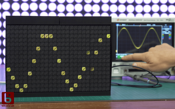
Oscilloscope And Microscope Augmented With Ghosts

Augmented reality saw a huge boom a few years ago, where an image of the real world has some virtual element layer displayed on top of it. To get this effect to work, however, you don’t need a suite of software and smart devices. [elad] was able to augment a microscope with the output from an oscilloscope, allowing him to see waveforms while working on small printed circuit boards with the microscope.

The build relies on a simplified version of the Pepper’s Ghost illusion. This works by separating two images with a semi-transparent material such as glass, placed at an angle. When looking through the material, the two images appear to blend together. [elad] was able to build a box that attaches to the microscope with a projection of the oscilloscope image augmented on the view of the microscope.

This looks like it would be incredibly useful for PCBs, especially when dealing with small SMD components. The project is split across two entries, the second of which is here. In one demonstration the oscilloscope image is replaced with a visual of a computer monitor, so it could be used for a lot more applications than just the oscilloscope, too. There aren’t a lot of details on the project page though, but with an understanding of Pepper’s Ghost this should be easily repeatable. If you need more examples, there are plenty of other builds that use this technique.

Continue reading “Oscilloscope And Microscope Augmented With Ghosts”

Recreating Fast Oscilloscopes Is A Slow Process

If you want to do something you’ve never done before, there are two broadly-defined ways of approaching it: either you learn everything you can about it and try to do it right the first time, or you get in there and get your hands dirty, and work out the details along the way. There’s a lot to be said for living life by the seat of your pants. Just ask anyone who found inspiration in the 11th hour of a deadline, simply because they had no other choice.

Ted Yapo didn’t have a lot of high-speed design knowledge when he set out to build an open-source multi-GHz sampling oscilloscope, but he didn’t let that stop him. Fast forward a year or so, and Ted’s ready to build his third prototype armed with all the hands-on practical knowledge he’s gained from building the first two.

At the 2019 Hackaday Superconference, Ted gave a talk about his journey into the high-stakes world of high-speed design. It’s an inspiring talk, and Ted gives a good look into everything he’s learned in trying to build a sampling ‘scope. We think you’ll appreciate not only Ted’s work, but also the ease with which he explains it all.

Continue reading “Recreating Fast Oscilloscopes Is A Slow Process”

Solving The Mysteries Of Grounding While Improving A Power Supply

Grounding problems and unwanted noise in electrical systems can often lead to insanity. It can seem like there’s no method to the madness when an electrical “gremlin” caused by one of these things pops its head out. When looking more closely, however, these issues have a way of becoming more obvious. In a recent video, [Fesz Electronics] shows us how to investigate some of these problems by looking at a small desktop power supply, modelling it in LTSpice, and reducing the noise on the power supply’s output.

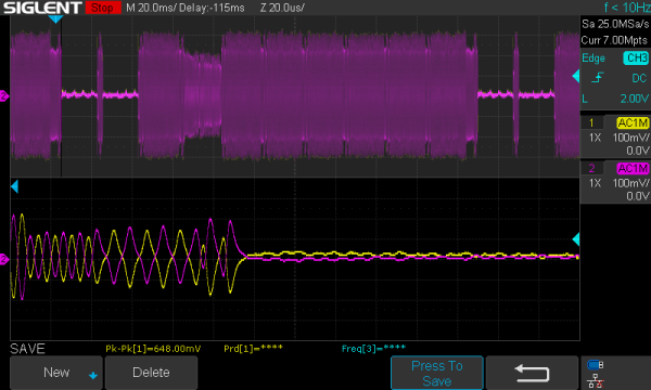
While everything in this setup is properly grounded, including the power supply and oscilloscope, the way the grounding systems interact can contribute to the high amount of noise. This was discovered by isolating the power supply from earth ground using electrical tape (not recommended as a long-term solution) and seeing that the noise was reduced. However, the ripple increased substantially, so a more permanent fix was needed. For that, the power supply was modelled in LTSpice. This is where a key discovery was made: since all the parts of the power supply aren’t ideal, noise can be introduced from the actual real-life electrical behavior of some of the parts. In this case, it was non-ideal capacitance in the transformer.

According to the model, this power supply could be improved by adding a larger capacitor across the output leads, and also by increasing their inductance. A large capacitor was soldered in the power supply and an iron ferrule was added, which decreased the noise level from 100 mV to around 20. Still not perfect, but a much needed improvement to the simple power supply. If, on the other hand, you want to make sure you eliminate that transformer’s capacitance completely, you can always go with a transformerless power supply. That carries other risks, though.

Continue reading “Solving The Mysteries Of Grounding While Improving A Power Supply”