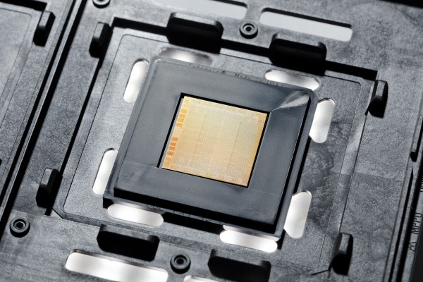
This week, IBM revealed their POWER10 CPU, which may not seem too exciting since it’s primarily aimed at big iron like mainframes and servers. The real news for most is that it is the first processor to be released that is based on the open Power ISA specification v3.1. This new version of the Power ISA adds a number of new instructions as well as the notion of optionality. It updates the v3.0 specification that was released in 2015, right after the founding of the OpenPOWER Foundation.
Currently, a number of open source designs for the Power ISA exists, including MicroWatt (Power v3.0, VHDL) and the similar ChiselWatt (written in Scala-based Chisel). In June of this year, IBM also released the VHDL code for the IBM A2 processor on Github. This is a multi-core capable, 4-way multithreaded 64-bit design, with silicon-implementations running at up to 2.3 GHz and using the Power ISA v2.06 specification.
Back in high school, all the serious gearheads used to brag about two things: their drag strip tickets, and their dynamometer reports. The former showed how fast their muscle car could cover a quarter-mile, while the latter was documentation on how much power their carefully crafted machine could deliver. What can I say; gas was cheap and we didn’t have the Internet to distract us.
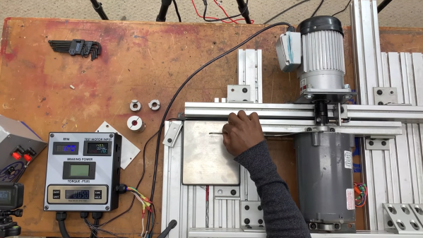
Bragging rights are not exactly what [Jeremy Fielding] has in mind for his DIY dynamometer, nor is getting the particulars on a big Detroit V8 engine. Rather, he wants to characterize small- to medium-sized electric motors, with an eye toward repurposing them for different projects. To do this, he built a simple jig to measure the two parameters needed to calculate the power output of a motor: speed and torque. A magnetic tachometer does the job of measuring the motor’s speed, but torque proved a bit more challenging. The motor under test is coupled to a separate electric braking motor, which spins free when it’s not powered. A lever arm of known length connects to the braking motor on one end while bearing on a digital scale on the other. With the motor under test spun up, the braking motor is gradually powered, which rotates its housing and produces a force on the scale through the lever arm. A little math is all it takes for the mystery motor to reveal its secrets.
[Jeremy]’s videos are always instructional, and the joy he obviously feels at discovery is infectious, so we’re surprised to see that we haven’t featured any of his stuff before. We’ve seen our share of dynos before, though, from the tiny to the computerized to the kind that sometimes blows up.
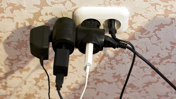
During my recent trip to Europe, I found out that converters were not as commonly sold as adapters, and for a good reason. The majority of the world receives 220-240 V single phase voltage at 50-60 Hz with the surprisingly small number of exceptions being Canada, Colombia, Japan, Taiwan, the United States, Venezuela, and several other nations in the Caribbean and Central America.
While the majority of countries have one defined plug type, several countries in Latin America, Africa, and Asia use a collection of incompatible plugs for different wall outlets, which requires a number of adapters depending on the region traveled.
Although there is a fair degree of standardization among most countries with regards to the voltage used for domestic appliances, what has caused the rift between the 220-240 V standard and the 100-127 V standards used in the remaining nations?
One of the nice things about a road trip is you often get to see something that really surprises you. A recent trip through Texas may have resulted in my second most surprising sighting. There’s a strange tower that looks oddly like a Tesla tower in the middle of rural Texas, right off the main interstate. What is it? Although Google did answer the question — sort of — I’m still not sure how legitimate its stated purpose is.
First Sighting
I was driving between Wimberly and Frisco — two towns that aren’t exactly household names outside of Texas. Near Milford, there’s a very tall structure that looks like a giant mechanical mushroom on top of a grain silo. If the mushroom were inverted or pointing towards the horizon, it would be easy to imagine it was some very odd antenna. This dish, however, is pointed right down its own odd-shaped mast. The top of the thing sure looks like the top of a Van de Graf generator.
A computer processor uses a so-called Instruction Set Architecture to talk with the world outside of its own circuitry. This ISA consists of a number of instructions, which essentially define the functionality of that processor, which explains why so many ISAs still exist today. It’s hard to find that one ISA that works for as many distinct use cases as possible, after all.
A fairly new ISA is RISC-V, the first version of which was created back in 2010 at the University of California, Berkeley. Intended to be a fully open ISA, targeting both students (as a learning tool) and industrial users, it is claimed to incorporate a number of design choices that should make it more attractive for a number of applications.
In this article I’ll take a look behind the marketing to take stock of how exactly RISC-V differs from other open ISAs, including Power, SPARC and MIPS.
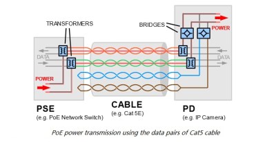
A remote Ethernet device needs two things: power and Ethernet. You might think that this also means two cables, a beefy one to carry the current needed to run the thing, and thin little twisted pairs for the data. But no!
Power over Ethernet (PoE) allows you to transmit power and data over to network devices. It does this through a twisted pair Ethernet cabling, which allows a single cable to drive the two connections. The main advantage of using PoE as opposed to having separate lines for power and data is to simplify the process of installation – there’s fewer cables to keep track of and purchase. For smaller offices, the hassle of having to wire new circuits or a transformer for converted AC to DC can be annoying.
PoE can also be an advantage in cases where power is not easily accessible or where additional wiring simply is not an option. Ethernet cables are often run in the ceiling, while power runs near the floor. Furthermore, PoE is protected from overload, short circuiting, and delivers power safely. No additional power supplies are necessary since the power is supplied centrally, and scaling the power delivery becomes a lot easier.
Devices Using PoE
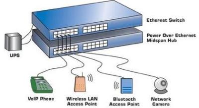
[via PowerOverEthernet.com]VoIP phones are becoming increasingly prevalent as offices are opting to provide power for phones from a central supply rather than hosting smaller power supplies to supply separate phones. Smart cameras – or IP cameras – already use Ethernet to deliver video data, so using PoE simplifies the installation process. Wireless access points can be easily connected to Ethernet through a main router, which is more convenient than seeking out separate power supplies.
Other devices that use PoE include RFID readers, IPTV decoders, access control systems, and occasionally even wall clocks. If it already uses Ethernet, and it doesn’t draw too much power, it’s a good candidate for PoE.
On the supply side, given that the majority of devices that use PoE are in some form networking devices, it makes sense that the main device to provide power to a PoE system would be the Ethernet switch. Another option is to use a PoE injector, which works with non-PoE switches to ensure that the device is able to receive power from another source than the switch.
How it Works
Historically, PoE was implemented by simply hooking extra lines up to a DC power supply. Early power injectors did not provide any intelligent protocol, simply injecting power into a system. The most common method was to power a pair of wires not utilized by 100Base-TX Ethernet. This could easily destroy devices not designed to accept power, however. The IEEE 802.3 working group started their first official PoE project in 1999, titled the IEE 802.3af.
[via Fiber Optic Communication]This standard delivered up to 13 W to a powered device, utilizing two of the four twisted pairs in Ethernet cabling. This was adequate power for VoIP phones, IP cameras, door access control units, and other devices. In 2009, the IEEE 802.3 working group released the second PoE standard, IEEE 802.3at. This added a power class that could deliver up to 25.5 W, allowing for pan and tilt cameras to use the technology.
While further standards haven’t been released, proprietary technologies have used the PoE term to describe their methods of power delivery. A new project from the IEEE 802.3 working group was the 2018 released IEEE 802.3bt standard that utilizes all four twisted pairs to deliver up to 71 W to a powered device.
But this power comes at a cost: Ethernet cables simply don’t have the conductive cross-section that power cables do, and resistive losses are higher. Because power loss in a cable is proportional to the squared current, PoE systems minimize the current by using higher voltages, from 40 V to 60 V, which is then converted down in the receiving device. Even so, PoE specs allow for 15% power loss in the cable itself. For instance, your 12 W remote device might draw 14 W at the wall, with the remaining 2 W heating up your crawlspace. The proposed 70 W IEEE 802.3bt standard can put as much as 30 W of heat into the wires.
The bigger problem is typically insufficient power. The 802.4af PoE standard maximum power output is below 15.4 W (13 W delivered), which is enough to provide power for most networking devices. For higher power consumption devices, such as network PTZ cameras, this isn’t the case.
Although maximum power supply is specified in the standards, having a supply that supplied more power is necessary will not affect the performance of the device. The device will draw as much current as necessary to operate, so there is no risk of overload, just hot wires.
So PoE isn’t without its tradeoffs. Nevertheless, there’s certainly a lot of advantages to accepting PoE for devices, and of course we welcome a world with fewer wires. It’s fantastic for routers, phones, and their friends. But when your power-hungry devices are keeping you warm at night, it’s probably time to plug them into the wall.
Without warning on an early August evening a significant proportion of the electricity grid in the UK went dark. It was still daylight so the disruption caused was not as large as it might have been, but it does highlight how we take a stable power grid for granted.
The story is a fascinating one of a 76-second chain of unexpected shutdown events in which individual systems reacted according to their programming, resulted in a partial grid load shedding — what we might refer to as a shutdown. [Mitch O’Neill] has provided an analysis of the official report which translates the timeline into easily accessible text.
It started with a lightning strike on a segment of the high-voltage National Grid, which triggered a transient surge and a consequent disconnect of about 500MW of small-scale generation such as solar farms. This in turn led to a large offshore wind farm deloading itself, and then a steam turbine at Little Barford power station. The grid responded by bringing emergency capacity online, presumably including the Dinorwig pumped-storage plant we visited back in 2017.
Perhaps the most interesting part followed is that the steam turbine was part of a combined cycle plant, processing the heat from a pair of gas turbine generators. As it came offline it caused the two gas turbines feeding it to experience high steam pressure, meaning that they too had to come offline. The grid had no further spare capacity at this point, and as its frequency dropped below a trigger point of 48.8 Hz an automatic deloading began, in effect a controlled shutdown of part of the grid to reduce load.