Making Sure Your Patch Cables Are Ready For RF Work

How do you know that your patch cables are good? For simple jumper wires, a multimeter is about all you need to know for sure. But things can get weird in the RF world, in which case you might want to keep these coaxial patch cable testing tips in mind.

Of course, no matter how high the frequency, the basics still apply, and [FesZ] points out in the video below that you can still get a lot of mileage out of the Mark 1 eyeball and a simple DMM. Visual inspection of the cable and terminations can reveal a lot, as can continuity measurements on both the inner and outer conductors. Checking for shorts between conductors is important, too. But just because the cable reads good at DC doesn’t mean that problems aren’t still lurking. That’s when [FesZ] recommends breaking out a vector network analyzer like the NanoVNA. This tool will allow you to measure the cable’s attenuation and return loss parameters across the frequency range over which the cable will be used.

For stubborn problems, or just for funsies, there’s also time-domain reflectometry, which can be done with a pulse generator and an oscilloscope to characterize impedance discontinuities in the cable. We’ve covered simple TDR measurement techniques before, but [FesZ] showed a neat trick called time-domain transformation, which uses VNA data to visualize the impedance profile of the whole cable assembly, including its terminations.

Continue reading “Making Sure Your Patch Cables Are Ready For RF Work”

Radio Frequency Burns, Flying A Kite, And You

Most hams can tell you that it’s possible to get a nasty RF burn if you accidentally touch an antenna while it’s transmitting. However, you can also cop a nasty surprise on the receiving end if you’re not careful, as explained in a video from [Grants Pass TV Repair].

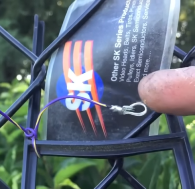
It’s hard to see in a still image, but the RF burns from the kite antenna actually generate a little puff of smoke on contact.

An experiment was used to demonstrate this fact involving a kite and a local AM broadcaster. A simple calculation revealed that an antenna 368 feet and 6 inches long would be resonant with the KAJO Radio signal at 1.270 MHz. At half the signal’s wavelength, an antenna that long would capture plenty of energy from the nearby broadcast antenna.

Enter the kite, which served as a skyhook to loft an antenna that long. With the wire in the air picking up a strong signal from the AM radio tower, it was possible to get a noticable RF burn simply by touching the end of the antenna.

The video explains that this is a risky experiment, but not only because of the risk of RF burn itself. It’s also easy to accidentally get a kite tangled in power lines, or to see it struck by lightning, both of which would create far greater injuries than the mild RF burn seen in the video. In any case, even if you know what you’re doing, you have to be careful when you’re going out of your way to do something dangerous in the first place.

AM radio towers aren’t to be messed with; they’ve got big power flowing. Video after the break.

Continue reading “Radio Frequency Burns, Flying A Kite, And You”

Don’t Let The Baluns Float Over Your Head

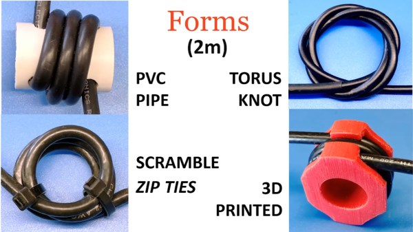
Most ham radio operators will build an antenna of some sort when they first start listening or transmitting, whether it’s a simple dipole, a beam antenna like a Yagi, or even just a random wire vertical antenna. All of these will need to be connected feedline of some sort, and in the likely event you reach for some 50-ohm coax cable you’ll also need a balun to reduce noise or unwanted radiation. Don’t be afraid of extra expenses when getting into this hobby, though, as [W6NBC] demonstrates how to construct an “ugly balun” out of the coax wire itself (PDF).

The main purpose of a balun, a contraction of “balanced-unbalanced” is to convert an unbalanced transmission line to a balanced one. However, as [W6NBC] explains, this explanation obscures much of what baluns are actually doing. In reality, they take a three-wire system (the coax) and convert it to a two-wire system (the antenna), which keeps all of the electrical noise and current on the shield wire of the coax from interfering with the desirable RF on the interior of the coax.

This might seem somewhat confusing on the surface, as coax wires only have a center conductor and a shield wire, but thanks to the skin effect which drives currents to the outside of the conductor, the shield wire effectively becomes two conductors when taking into account its inner and outer surfaces. At these high frequencies the balun is acting as a choke which keeps these two high-frequency conductors separate from one another, and keeps all the noise on the outside of the shield wire and out of the transmitter or receiver.

Granted, the world of high-frequency radio circuits can get quite complex and counter-intuitive and, as we’ve shown before, can behave quite unexpectedly when compared to DC or even mains-frequency AC. But a proper understanding of baluns and other types of transformers and the ways they interact with RF can be a powerful tool to have. We’eve even seen other hams use specialty transformers like these to make antennas out of random lengths and shapes of wire.

Continue reading “Don’t Let The Baluns Float Over Your Head”

Self-Driving Or Mind Control? Which Do You Prefer?

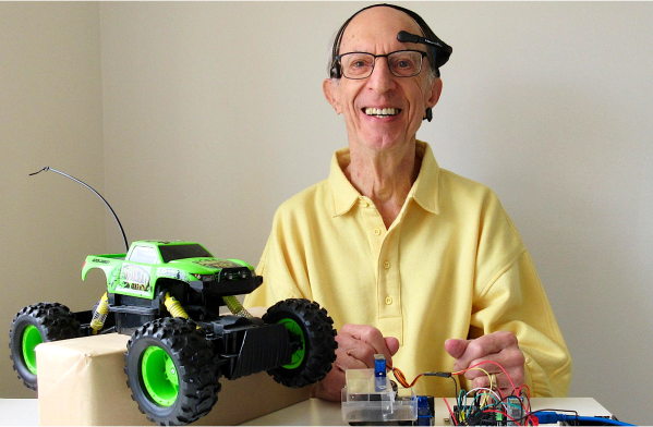
We know you love a good biohack as much as we do, so we thought you would like [Tony’s] brainwave-controlled RC truck. Instead of building his own electroencephalogram (EEG), he thought he would use NeuroSky’s MindWave. EEGs are pretty complex, multi-frequency waves that require some fairly sophisticated circuitry and even more sophisticated signal processing to interpret. So, [Tony] thought it would be nice to off-load a bit of that heavy-lifting, and luckily for him, the MindWave headset is fairly hacker-friendly.

EEGs are a very active area of research, so some of the finer details of the signal are still being debated. However, It appears that attention can be quantified by measuring alpha waves which are EEG content between 8-10 Hz. And it seems as though eye blinks can be picked from the EEG as well. Conveniently, the MindWave exports these energy levels to an accompanying smartphone application which [Tony] then links to his Arduino over Bluetooth using the ever-so-popular HC-05 module.

To control the car, he utilized the existing remote control instead of making his own. Like most people, [Tony] thought about hooking up the Arduino pins to the buttons on the remote control, thereby bypassing the physical buttons, but he noticed the buttons were a bit smaller than he was comfortable soldering to and he didn’t want to risk damaging the circuit board. [Tony’s] RC truck has a pistol grip transmitter, which inspired a slightly different approach. He mounted the servo onto the controller’s wheel mechanism, allowing him to control the direction of the truck by rotating the wheel using the servo. He then fashioned another servo onto the transmitter such that the servo could depress the throttle when it rotates. We thought that was a pretty nifty workaround.

Cool project, [Tony]! We’ve seen some cool EEG Hackaday Prize entries before. Maybe this could be the next big one.

Continue reading “Self-Driving Or Mind Control? Which Do You Prefer?”

How Early Radio Receivers Worked

If you’ve ever built a crystal radio, there’s something magical about being able to pull voices and music from far away out of thin air. If you haven’t built one, maybe you should while there’s still something on the AM band. Of course, nowadays the equivalent might be an SDR. But barring a computer solution, there are not many ways to convert radio waves into intelligence. From a pocket radio to advanced RADAR to a satellite in orbit, receiving a radio wave is accomplished in pretty much the same way.

There are, however, many ways to modulate and demodulate that radio wave. Of course, an AM radio works differently than an FM radio. A satellite data downlink works differently, too. But the process of capturing the radio wave from the air and getting them into a form ready for further processing hasn’t changed much over the years.

In this article, I’ll talk about the most common radio receiver architectures you may have seen in years past, and next week I’ll talk about modern architectures. Either way, understanding receiver architectures will help you design new radios or troubleshoot them.

Continue reading “How Early Radio Receivers Worked”

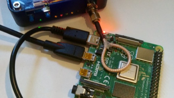
Raspberry Pi 4 HDMI Is Jamming Its Own WiFi

Making upgrades to a popular product line might sound like a good idea, but adding bigger/better/faster parts to an existing product can cause unforeseen problems. For example, dropping a more powerful engine in an existing car platform might seem to work at first until people start reporting that the increased torque is bending the frame. In the Raspberry Pi world, it seems that the “upgraded engine” in the Pi 4 is causing the WiFi to stop working under specific circumstances.

[Enrico Zini] noticed this issue and attempted to reproduce exactly what was causing the WiFi to drop out, and after testing various Pi 4 boards, power supplies, operating system version, and a plethora of other variables, the cause was isolated to the screen resolution. Apparently at the 2560×1440 setting using HDMI, the WiFi drops out. While you could think that an SoC might not be able to handle a high resolution, WiFi, and everything else this tiny computer has to do at once. But the actual cause seems to be a little more interesting than a simple system resources issue.

[Mike Walters] on a Twitter post about this issue probed around with a HackRF and discovered a radio frequency issue. It turns out that at this screen resolution, the Pi 4 emits some RF noise which is exactly in the range of WiFi channel 1. It seems that the Pi 4 is acting as a WiFi jammer on itself.

This story is pretty new, so hopefully the Raspberry Pi Foundation is aware of the issue and working on a correction. For now, though, it might be best to run a slightly lower resolution if you’re encountering this problem.

Understanding Modulated RF With [W2AEW]

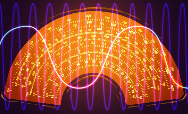
There was a time — not long ago — when radio and even wired communications depended solely upon Morse code with OOK (on off keying). Modulating RF signals led to practical commercial radio stations and even modern cell phones. Although there are many ways to modulate an RF carrier with voice AM or amplitude modulation is the oldest method. A recent video from [W2AEW] shows how this works and also how AM can be made more efficient by stripping the carrier and one sideband using SSB or single sideband modulation. You can see the video, below.

As is typical of a [W2AEW] video, there’s more than just theory. An Icom transmitter provides signals in the 40 meter band to demonstrate the real world case. There’s discussion about how to measure peak envelope power (PEP) and comparison to average power and other measurements, as well.

Continue reading “Understanding Modulated RF With [W2AEW]”