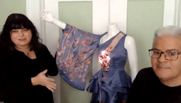
[Hal Rodriguez] and [Sahrye Cohen] of Amped Atelier focus on creating interactive wearable garments with some fairly high standards. Every garment must be pretty, and has to either be controllable by the wearer, through a set of sensors, or even by the audience via Bluetooth. Among their past creations are a dress with color sensors and 3D-printed scales on the front that change color, and a flowing pantsuit designed for a dancer using an accelerometer to make light patterns based on her movements.
Conductive Melody — a wearable musical instrument that is the focus of [Sahrye] and [Hal]’s Remoticon 2021 talk — was created for a presentation at Beakerhead Festival, a multi-day STEAM-based gathering in Calgary. [Sahrye] and [Hal] truly joined forces for this one, because [Sahrye] is all about electronics and costuming, and [Hal] is into synths and electronic music. You can see the demo in the video after the break.
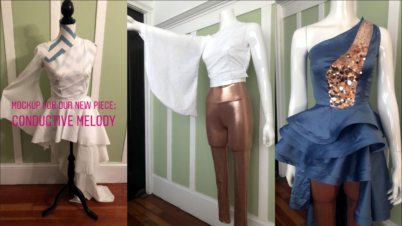
The dress’s form is inspired by classical instruments and the types of clothing that they in turn inspired, such as long, generous sleeves for harp players and pianists. So [Hal] and [Sahrye] dreamed up a dress with a single large playable sleeve that hangs down from the mid- and upper arm. The sleeve is covered with laser-cut conductive fabric curlicues that look like a baroque interpretation of harp strings. Play a note by touching one of these traces, and the lights on the front of the dress will move in sync with the music.
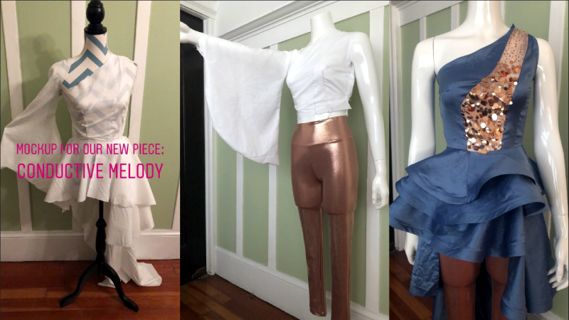 [Sahrye] started the dress portion of Conductive Melody with a sketch of the garment’s broad strokes, then painted a more final drawing with lots of detail. Then she made a muslin, which is kind of the breadboard version of a project in garment-making where thin cotton fabric is used to help visualize the end result. Once satisfied with the fit, [Sahrye] then made the final dress out of good fabric. And we mean really good fabric — silk, in this case. Because as [Sahrye] says, if you’re going to make a one-off, why not make as nicely as possible? We can totally get behind that.
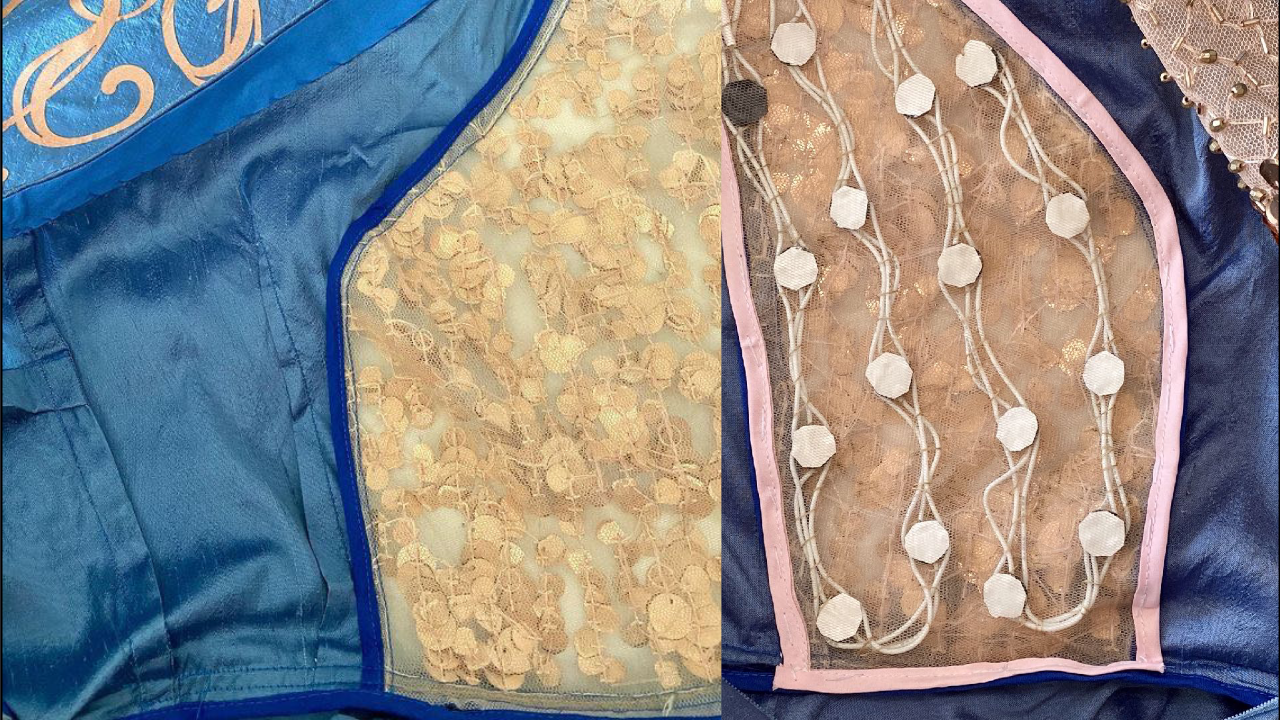
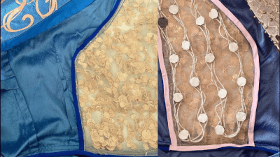 [Sahrye] says she is always thinking about how a wearable will be worn, and how it will be washed or otherwise cared for. That sequined and semi-sheer section of the bodice hides the LEDs and their wiring quite well, while still being comfortable for the wearer.
Inside the sleeve is an MPRP121 capacitive touch sensor and an Arduino that controls the LEDs and sends the signals to a Raspberry Pi hidden among the ruffles in the back of the dress.
The Pi is running Piano Genie, which can turn eight inputs into an 88-key piano in real time. When no one is playing the sleeve, the lights have a standby mode of mellow yellows and whites that fade in and out slowly compared to the more upbeat rainbow of musical mode.
We love to see wearable projects — especially such fancy creations! — but we know how finicky they can be. Among the lessons learned by [Sahrye] and [Hal]: don’t make your conductive fabric traces too thin, and silver conductive materials may tarnish irreparably. We just hope they didn’t have to waste too much conductive fabric or that nice blue silk to find this out.
Continue reading “REMOTICON 2021 // Hal Rodriguez And Sahrye Cohen Combine Couture And Circuitry” →