Heathkit Signal Generator Gets An Update

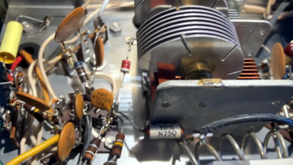
[DTSS_Smudge] correctly intuits that if you are interested in an old Heathkit signal generator, you probably already know how to solder. So, in a recent video, he focused on the components he decided to update for safety and other reasons. Meanwhile, we get treated to a nice teardown of this iconic piece of test gear.

If you didn’t grow up in the 1960s, it seems strange that the device has a polarized line cord with one end connected to the chassis. But that used to be quite common, just like kids didn’t wear helmets on bikes in those days.

A lot of TVs were “hot chassis” back then, too. We were always taught to touch the chassis with the back of your hand first. That way, if you get a shock, the associated muscle contraction will pull your hand away from the electricity. Touching it normally will make you grip the offending chassis hard, and you probably won’t be able to let go until someone kindly pulls the plug or a fuse blows.

These signal generators were very common back in the day. A lot of Heathkit gear was very serviceable and more affordable than the commercial alternatives. In 1970, these cost about $32 as a kit or $60 already built. While $32 doesn’t sound like much, it is equivalent to $260 today, so not an impulse buy.

Some of the parts are simply irreplaceable. The variable capacitor would be tough to source since it is a special type. The coils would also be tough to find replacements, although you might have luck rewinding them if it were necessary.

We are spoiled today with so many cheap quality instruments available. However, there was something satisfying about building your own gear and it certainly helped if you ever had to fix it.

There was so much Heathkit gear around that even though they’ve been gone for years, you still see quite a few units in use. Not all of their gear had tubes, but some of our favorite ones did.

Fail Of The Week: The Case Of The Curiously Colored Streetlights

What color are the street lights in your town? While an unfortunate few still suffer under one of the awful colors offered by vapor discharge lamps, like the pink or orange of sodium or the greenish-white of mercury, most municipalities have moved to energy-saving LED streetlights, with a bright white light that’s generally superior in every way. Unless, of course, things go wrong and the lights start to mysteriously change colors.

If you’ve noticed this trend in your area, relax; [NanoPalomaki] has an in-depth and surprisingly interesting analysis of why LED streetlights are changing colors. After examining a few streetlights removed from service thanks to changing from white to purple, he discovered a simple explanation. White LEDs aren’t emitting white light directly; rather, the white light comes from phosphors coating the underlying LED, which emits a deep blue light. The defunct units all showed signs of phosphor degradation. In some cases, the phosphors seemed discolored, as if they experienced overheating or chemical changes. In other LEDs the phosphor layer was physically separated from the backing, exposing the underlying LEDs completely. The color of these damaged modules was significantly shifted toward the blue end of the spectrum, which was obviously why they were removed from service.

Now, a discolored LED here and there does not exactly constitute a streetlight emergency, but it’s happening to enough cities that people are starting to take notice. The obvious solution would be for municipalities to replace the dodgy units Even in the unlikely event that a city would get some compensation from the manufacturer, this seems like an expensive proposition. Luckily, [NanoPalomaki] tested a solution: he mixed a wideband phosphor into a UV-curable resin and painted it onto the lens of each defective LED in the fixture. Two coats seemed to do the trick.

We have to admit that we have a hard time visualizing a city employee painstakingly painting LEDs when swapping out a fixture would take an electrician a few minutes, but at least it’s an option. And, it’s something for hobbyists and homeowners faced with the problem of wonky white LEDs to keep in mind too.

Continue reading “Fail Of The Week: The Case Of The Curiously Colored Streetlights”

Two hands hold a rounded rectangular case with a small lollipop-shaped cutout. The case is dark grey with a bit of white protruding between the two halves in the middle.

Add USB-C To Your AirPods The Easy Way

While the death of Apple’s Lightning Connector can’t come soon enough, swapping the ports on their products as “category-defining innovations” seems a bit of a stretch. [Ken Pillonel] has designed a set of streamlined, repairable, USB-C adapters for the AirPods, AirPods Pro, and AirPods Max that show Apple what innovation really means.

If you’ve followed [Pillonel]’s work in the past, you’ll know he’s as a big a fan of repairability as we are here, so this isn’t just a cheap knockoff dongle that’ll be in the trash as fast as your counterfeit wireless earbuds. In the video below, he walks us through his quest start-to-finish to design something compact that gives you all the joys of USB-C without the pain of buying a whole new set of headphones.

We like the iteration on the connector, showing that flexible circuits can do some amazing things, but are still subject to failure at extreme angles. Using a combination of 3D printing, a cool robot sandblasting machine, a pick-and-place, and some old fashioned hand soldering, [Pillonel] treats us to a polished final product that’s put together with actual screws and not adhesive. His designs are all open source, so you can DIY, or he sells finished copies in his shop if you want to give one to your less-than-techy relatives.

[Pillonel] may seem familiar as he’s the guy who added USB-C to the iPhone before Apple and redesigned the AirPods Pro case for repairability. Apple is getting better about repair in some of its devices, for sure, but unsurprisingly, hackers do it better.

Continue reading “Add USB-C To Your AirPods The Easy Way”

Hands-on With New IPhone’s Electrically-Released Adhesive

There’s a wild new feature making repair jobs easier (not to mention less messy) and iFixit covers it in their roundup of the iPhone 16’s repairability: electrically-released adhesive.

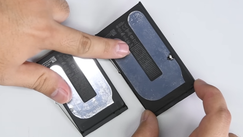
Here’s how it works. The adhesive looks like a curved strip with what appears to be a thin film of aluminum embedded into it. It’s applied much like any other adhesive strip: peel away the film, and press it between whatever two things it needs to stick. But to release it, that’s where the magic happens. One applies a voltage (a 9 V battery will do the job) between the aluminum frame of the phone and a special tab on the battery. In about a minute the battery will come away with no force, and residue-free.

There is one catch: make sure the polarity is correct! The adhesive releases because applying voltage oxidizes aluminum a small amount, causing Al3+ to migrate into the adhesive and debond it. One wants the adhesive debonded from the phone’s frame (negative) and left on the battery. Flipping the polarity will debond the adhesive the wrong way around, leaving the adhesive on the phone instead.

Some months ago we shared that Apple was likely going to go in this direction but it’s great to see some hands-on and see it in action. This adhesive does seem to match electrical debonding offered by a company called Tesa, and there’s a research paper describing it.

A video embedded below goes through the iPhone 16’s repairability innovations, but if you’d like to skip straight to the nifty new battery adhesive, that starts at the 2:36 mark.

Continue reading “Hands-on With New IPhone’s Electrically-Released Adhesive”

Fun And Failure

My sister is a beekeeper, or maybe a meta-beekeper. She ends up making more money by breeding and selling new queen bees to other beekeepers than she does by selling honey, but that doesn’t mean that she doesn’t also process the sweet stuff from time to time. She got a free steam-heated oscillating hot knife, used for cutting the waxy caps off of the tops of the cells before spinning the combs down to extract honey, and she thought it might be easier to use than her trusty hand-held electric hot knife.

The oscillating knife, which was built something like a century ago, hadn’t been used in decades. All of the grease had turned to glue, and the large v-belt wheel that made it go was hard to turn by hand, and the motor was missing anyway. So she gave it to my father and me as a project. How could we resist?

We found the original manual on the Internet, which said that it would run from any 1/2 hp motor, or could be optionally driven by a takeoff wheel from a tractor – unfortunately not an option in my sister’s honey house. But we did find a 3/4 hp bench grinder at Harbor Freight that conveniently fit inside the case, and bought the smallest v-belt pulley wheel that would fit the grinder’s arbor. We thought we were geniuses, but when we hooked it all up, it just stalled.

We spent more than a few hours taking the mechanism apart. It was basically an eccentric shaft with a bearing on the end, and the bearing ran back and forth in the groove of a sliding mechanism that the knife blade attached to. As mentioned above, everything was gunked, so we took it all apart. The bearing was seized, so we freed that up by getting the sand out of the balls. The bearing couldn’t move freely in the slide either, but we filed that down until it just moved freely without noticeable play. We added grease from this century, and reassembled it. It turned fine by hand.

But with the belt and motor attached, the mechanism still had just enough friction to stall out the motor. Of course we wrapped some rope around the shaft and pull-started it, and it made a hell of a racket, nearly vibrated itself off the table, and we could see that the marvelous zinc-coated frame that held it all together was racking under the tension. It would require a wholly new housing to be viable, and we hadn’t even figured out a source of steam to heat the knife.

In short, it was more trouble than it was worth. So we packed up the bench grinder in the original container, and returned it no-worse-for-wear to the Freight. But frankly, we had a fantastic time playing around with a noble machine from a long-gone past. We got it “working” even if that state was unworkable, and we were only out the cost of the small v-belt pulley. Who says all of your projects have to be a success to be fun?

Unusual Tool Gets An Unusual Repair

In today’s value-engineered world, getting a decade of service out of a cordless tool is pretty impressive. By that point you’ve probably gotten your original investment back, and if the tool gives up the ghost, well, that’s what the e-waste bin is for. Not everyone likes to give up so easily, though, which results in clever repairs like the one that brought this cordless driver back to life.

The Black & Decker “Gyrodriver,” an interesting tool that is controlled with a twist of the wrist rather than the push of a button, worked well for [Petteri Aimonen] right up until the main planetary gear train started slipping thanks to stripped teeth on the plastic ring gear. Careful measurements of one of the planetary gears to determine parameters like the pitch and pressure angle of the teeth, along with the tooth count on both the planet gear and the stripped ring.

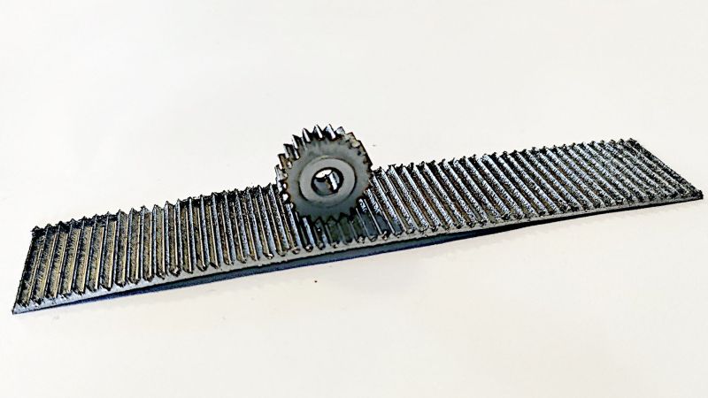
Here, most of us would have just 3D printed a replacement ring gear, but [Petteri] went a different way. He mentally rolled the ring gear out, envisioning it as a rack gear. To fabricate it, he simply ran a 60° V-bit across a sheet of steel plate, creating 56 parallel grooves with the correct pitch. Wrapping the grooved sheet around a round form created the ring gear while simultaneously closing the angle between teeth enough to match the measured 55° tooth angle in the original. [Petteri] says he soldered the two ends together to form the ring; it looks more like a weld in the photos, but whatever it was, the driver worked well after the old plastic teeth were milled out and the new ring gear was glued in place.

We think this is a really clever way to make gears, which seems like it would work well for both internal and external teeth. There are other ways to do it, of course, but this is one tip we’ll file away for a rainy day.

Fixing A Busted Fluke While Fighting A Wonky Schematic

Fluke meters have been around for a long, long time. Heck, we’ve got a Fluke 73 that we bought back in 1985 that’s still a daily driver. But just because they’ve been making them forever doesn’t mean they last forever, and getting a secondhand meter back in the game can be a challenge. That’s what [TheHWCave] learned with his revival of a wonky eBay Fluke 25, an effort that holds lessons for anyone in the used Fluke market.

Initial inspection of the meter showed encouragingly few signs of abuse, somewhat remarkable for something built for the military in the early 1980s. A working display allowed a few simple diagnostics revealing that the ammeter functions seemed to work, but not the voltmeter and ohmmeter functions. [TheHWCave]’s teardown revealed a solidly constructed unit with no obvious signs of damage or blown fuses. Thankfully, a service schematic was available online, albeit one with a frustrating lack of detail, confusing test point nomenclature, and contradictory component values.

Despite these hurdles, [TheHWCave] was able to locate the culprit: a bad fusible power resistor. Finding a direct replacement wasn’t easy given the vagaries of the schematic and the age of the instrument, but he managed to track down a close substitute cheap enough to buy in bulk. He searched through 40 units to find the one closest to the listed specs, which got the meter going again. Fixing the bent pin also gave the meter back its continuity beeper, always a mixed blessing.

If you’re in the market for a meter but can’t afford the Fluke name, picking up a busted meter and fixing it up like this might be one way to go. But are they really worth the premium? Well, kinda yes.

Continue reading “Fixing A Busted Fluke While Fighting A Wonky Schematic”