Improvements in methodology have dramatically dropped the cost of DNA sequencing in the last decade. In 2007, it cost around $10 million dollars to sequence a single genome. Today, there are services which will do it for as little as $1,000. That’s not to bad if you just want to examine your own DNA, but prohibitively expensive if you’re looking to experiment with DNA in the home lab. You can buy your own desktop sequencer and cut out the middleman, but they cost in the neighborhood of $50,000. A bit outside of the experimenter’s budget unless you’re Tony Stark.
 But thanks to the incredible work of [Alexander Sokolov], the intrepid hacker may one day be able to put a DNA sequencer in their lab for the cost of a decent oscilloscope. The breakthrough came as the result of those two classic hacker pastimes: reverse engineering and dumpster diving. He realized that the heavy lifting in a desktop genome sequencer was being done in a sensor matrix that the manufacturer considers disposable. After finding a source of trashed sensors to experiment with, he was able to figure out not only how to read them, but revitalize them so he could introduce a new sample.
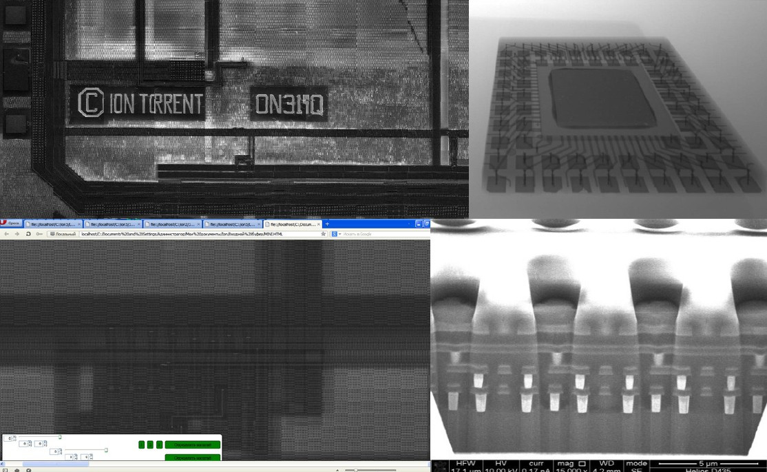
To start with, [Alexander] had to figure out how these “disposable” sensors worked. He knew they were similar in principle to a digital camera’s CCD sensor; but rather than having cells which respond to light, they read changes in pH level. The chip contains 10 million of these pH cells, and each one needs to be read individually hundreds of times to capture the entire DNA sequence.
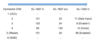
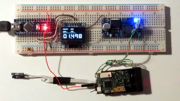
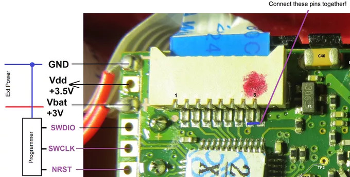
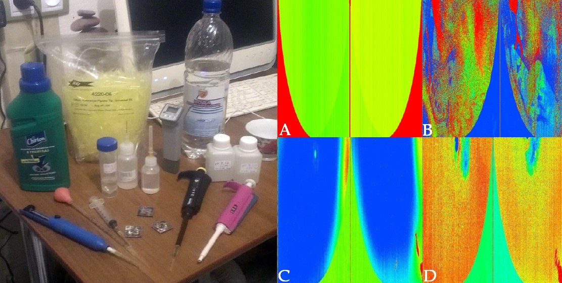 Enlisting the help of some friends who had experience reverse engineering silicon, and armed with an X-Ray machine and suitable optical microscope, he eventually figured out how the sensor matrix worked electrically. He then designed a board that reads the sensor and dumps the “picture” of the DNA sample to his computer over serial.
Once he could reliably read the sensor, the next phase of the project was finding a way to wash the old sample out so it could be reloaded. [Alexander] tried different methods, and after several wash and read cycles, he nailed down the process of rejuvenating the sensor so its performance essentially matches that of a new one. He’s currently working on the next generation of his reader hardware, and we’re very interested to see where the project goes.
This isn’t the first piece of DIY DNA hardware we’ve seen here at Hackaday, and it certainly won’t be the last. Like it or not, hackers are officially fiddling with genomes.