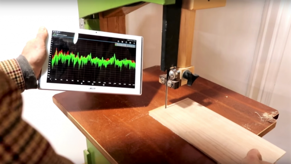
It’s the latest in instrumentation for the well-appointed shop — an acoustically coupled fast Fourier transform tachometer. Sounds expensive, but it’s really just using a smartphone spectrum analyzer app to indirectly measure tool speeds. And it looks like it could be incredibly handy.
Normally, non-contact tachometers are optically coupled, using photoreceptors to measure light flashing off of a shaft or a tool. But that requires a clear view of the machine, often putting hands far too close to the danger zone. [Matthias Wandel]’s method doesn’t require line of sight because it relies on a cheap spectrum analyzer app to listen to a machine’s sound. The software displays peaks at various frequencies, and with a little analysis and some simple math, the shaft speed of the machine can be determined. [Matthias] explains how to exclude harmonics, where to find power line hum, isolating commutator artifacts, and how to do all the calculations. You’ll need to know a little about your tooling to get the right RPM, and obviously you’ll be limited by the audio frequency response of your phone or tablet. But we think this is a great tip.
[Matthias] is no stranger to shop innovations and putting technology to work in simple but elegant ways. We wonder if spectrum analysis could be used to find harmonics and help with his vibration damping solution for a contractor table saw.
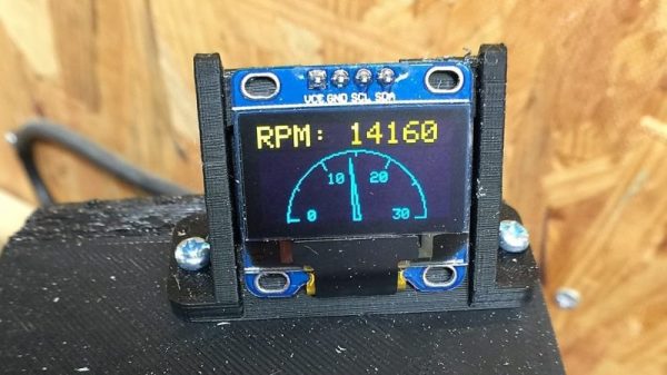
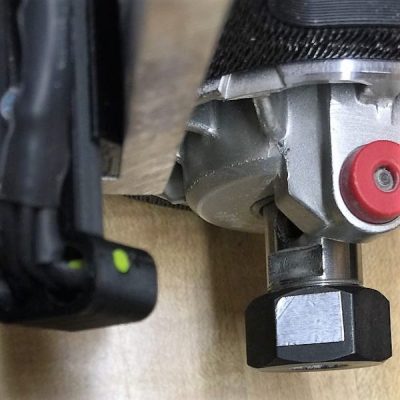 The CNC router in question is the popular Sienci, and the 3D-printed brackets for the photodiode and LED are somewhat specific for that machine. But [tmbarbour] has included STL files in his exhaustively detailed write-up, so modifying them to fit another machine should be easy. The sensor hangs down just far enough to watch a reflector on one of the flats of the collet nut; we’d worry about the reflector surviving tool changes, but it’s just a piece of shiny tape that’s easily replaced. The sensor feeds into a DIO pin on a Nano, and a small OLED display shows a digital readout along with an analog gauge. The display update speed is decent — not too laggy. Impressive build overall, and we like the idea of using a piece of PLA filament as a rivet to hold the diodes into the sensor arm.
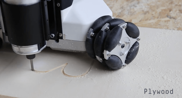
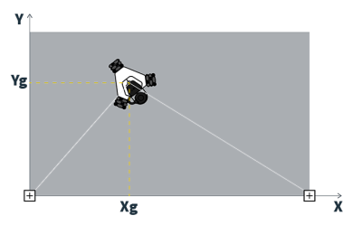 What really caught our eye is the Goliath’s unique positioning system. While most CNC machines have the luxury of end-stops or servomotors capable of precise positional control, the Goliath has two “base sensors” that are tethered to the top of the machine and mounted to the edge of the workpiece. Each sensor connects to the host computer via USB and uses vaguely termed “Radio Frequency technology” that provides a 100Hz update for the machine’s coordinate system. This setup is sure to beat out dead-reckoning for positional awareness, but details are scant on how it precisely operates. We’d love to know more if you’ve used a similar setup for local positioning as this is still a daunting task for indoor robots.