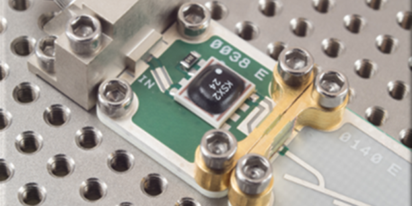
Friday Hack Chat: Simulating Analog

Simulation is a valuable tool for any hardware developer. Instead of building hardware for a long debugging session, you can emulate a microcontroller and blink your lights with some Javascript. Instead of working on a Bluetooth protocol for your fitness wearable, you can just whip up some Javascript and get it working that way. Once all your Javascript is in order, then you can finally move over to hardware. It saves development time, and it saves money.

But this is all digital. What do you do if you’re working on an analog system? Lucky for you, there’s a system built for analog and mixed-signal analysis, and it’s been around for decades. This week we’re talking all about PSpice, a simulator for analog analysis that will give you voltages and currents across every node in a schematic.

For this week’s Hack Chat, we’re going to be talking about PSpice with [Abha Jain] and [Alok Tripathi]. [Abha] has worked at Cadence for 19 years and has been part of the PSpice R&D team for the last decade. She’s an MTech in VLSI Design Tools and Technology and holds multiple EDA patents. [Alok] graduated in 1993 with a B. Tech in Electrical Engineering. He started working at the Department of Atomic Energy in 1993 as a power supply and control system designer for particle accelerators. Currently, he’s working with Cadence and is the Product Engineering Architect for PSpice and OrCAD.

For this Hack Chat, we’re going to be discussing the challenges of system-level simulation, improving reliability, yield, and productivity of circuit design, the issues of Spice simulation, and answer the question, ‘on an infinite grid of one Ohm resistors, what is the resistance between two nodes a knight’s move apart?’ You are, of course, encouraged to add your own questions to the Hack Chat. You can do that by leaving the questions as a comment on this Hack Chat’s event page.

join-hack-chat

Our Hack Chats are live community events on the Hackaday.io Hack Chat group messaging. This week it’s going down at an unusual time: 8 AM Pacific, Friday, March 30th  Want to know what time this is happening in your neck of the woods? Have a countdown timer!

Click that speech bubble to the right, and you’ll be taken directly to the Hack Chat group on Hackaday.io.

You don’t have to wait until Friday; join whenever you want and you can see what the community is talking about.

Amazing Mechanical Linkages And The Software To Design Them

Most of us are more bits-and-bytes than nuts-and-bolts, but we have the deepest appreciation for the combination of the two. So, apparently, does [rectorsquid]. Check out the design and flow of his rolling ball sculpture (YouTube, embedded below) to see what we mean. See how the arms hesitate just a bit as the ball is transferred? See how the upper arm gently places it on the ramp with a slight downward gesture? See how it’s done with one motor? There’s no way [rectorsquid] designed this on paper, right?

Of course he didn’t (YouTube). Instead, he wrote a simulator that lets him try out various custom linkages in real time. It’s a Windows-only application (sigh), but it’s free to use, while the video guides (more YouTube) look very comprehensive and give you a quick tour of the tool. Of special note is that [rectorsquid]’s software allows for sliding linkages, which he makes very good use of in the rolling ball sculpture shown here.

We’ve actually secretly featured [rectorsquid]’s Linkage software before, in this writeup of some amazing cosplay animatronic wings that used the program for their design. But we really don’t want you to miss out if you’re doing mechanical design and need something like this, or just want to play around.

If you’d like to study up on your nuts and bolts, check out our primer on the ubiquitous four-bar linkage, or pore through Hackaday looking for other great linkage-powered examples, like this automatic hacksaw or a pantograph PCB probe for shaky hands.

Anyone know of an open-source linkage simulator that can also output STL files for 3D printing? Or in any format that could be easily transformed into OpenSCAD? Asking for a “friend”.

Continue reading “Amazing Mechanical Linkages And The Software To Design Them”

Quantum Weirdness In Your Browser

I’ll be brutally honest. When I set out to write this post, I was going to talk about IBM’s Q Experience — the website where you can run real code on some older IBM quantum computing hardware. I am going to get to that — I promise — but that’s going to have to wait for another time. It turns out that quantum computing is mindbending and — to make matters worse — there are a lot of oversimplifications floating around that make it even harder to understand than it ought to be. Because the IBM system matches up with real hardware, it is has a lot more limitations than a simulator — think of programming a microcontroller with on debugging versus using a software emulator. You can zoom into any level of detail with the emulator but with the bare micro you can toggle a line, use a scope, and hope things don’t go too far wrong.

So before we get to the real quantum hardware, I am going to show you a simulator written by [Craig Gidney]. He wrote it and promptly got a job with Google, who took over the project. Sort of. Even if you don’t like working in a browser, [Craig’s] simulator is easy enough, you don’t need an account, and a bookmark will save your work.

It isn’t the only available simulator, but as [Craig] immodestly (but correctly) points out, his simulator is much better than IBM’s. Starting with the simulator avoids tripping on the hardware limitations. For example, IBM’s devices are not fully connected, like a CPU where only some registers can get to other registers. In addition, real devices have to deal with noise and the quantum states not lasting very long. If your algorithm is too slow, your program will collapse and invalidate your results. These aren’t issues on a simulator. You can find a list of other simulators, but I’m focusing on Quirk.

What Quantum Computing Is

As I mentioned, there is a lot of misinformation about quantum computing (QC) floating around. I think part of it revolves around the word computing. If you are old enough to remember analog computers, QC is much more like that. You build “circuits” to create results. There’s also a lot of difficult math — mostly linear algebra — that I’m going to try to avoid as much as possible. However, if you can dig into the math, it is worth your time to do so. However, just like you can design a resonant circuit without solving differential equations about inductors, I think you can do QC without some of the bigger math by just using results. We’ll see how well that holds up in practice.

Continue reading “Quantum Weirdness In Your Browser”

Nematoduino: A Roundworm Neural Model On An Arduino

When it comes to building a neural network to simulate complex behavior, Arduino isn’t exactly the first platform that springs to mind. But when your goal is to model the behavior of an organism with only a handful of neurons, the constraints presented by an Arduino start to make sense.

It may be the most important non-segmented worm you’ve never heard of, but Caenorhabditis elegans, mercifully abbreviated C. elegans, is an important model organism for neurobiology, having had its entire nervous system mapped in 2012. [Nathan Griffith] used this “connectome” to simulate a subset of the diminutive nematode’s behaviors, specifically movements toward attractants and away from obstacles. Riding atop a small robot chassis, the Arduino sends signals to the motors when the model determines it’s time to fire the virtual worm’s muscles. An ultrasonic sensor stands in for the “nose touch” neurons of the real worm, and when the model is not busy avoiding a touch, it’s actively seeking something to eat using the “chemotaxis” behavior. The model is up on GitHub and [Nathan] hopes it provides an approachable platform for would-be neuroroboticists.

This isn’t the first time someone has modeled the nematode’s connectome in silico, but kudos to [Nathan] for accomplishing it within the constraints an Arduino presents.

Continue reading “Nematoduino: A Roundworm Neural Model On An Arduino”

Emulate ICs In Python

Most people who want to simulate logic ICs will use Verilog, VHDL, or System Verilog. Not [hsoft]. He wanted to use Python, and wrote a simple Python framework for doing just that. You can find the code on GitHub, and there is an ASCII video that won’t embed here at Hackaday, but which you can view at ASCIInema.

Below the break we have an example of “constructing” a circuit in Python using ICemu:

Continue reading “Emulate ICs In Python”

Building A Working Game Of Tetris In Conway’s Game Of Life

If you haven’t been following along with Conway’s Game of Life, it’s come a long way from the mathematical puzzle published in Scientific American in 1970. Over the years, mathematicians have discovered a wide array of constructs that operate within Life’s rules, including many that can be leveraged to perform programming functions — logic gates, latches, multiplexers, and so on. Some of these creations have gotten rather huge and complicated, at least in terms of Life cells. For instance, the OTCA metapixel is comprised of 64,691 cells and has the ability to mimic any cellular automata found in Life.

A group of hackers has used OTCA metapixels to create a Tetris game out of Life elements. The game features all 7 shapes as well as the the movement, rotation, and drops one would expect. You can even preview the next piece. The game is the creation of many people who worked on individual parts of the larger program. They built a RISC computer out of Game of Life elements, as well as am assembler and compiler for it, with the OTCA metapixels doing the heavy lifting. (The image at the top of the post is the program’s data synchronizer.

Check out the project’s source code on GitHub, and use this interpreter. Set the RAM to 3-32 and hit run.

For a couple of other examples of Life creations, check out the Game of Life clock and music synthesized from Life automata we published earlier.

InstantCAD Promises Faster Iterative Design

The design process for any product is necessarily an iterative one. Often, a prototype is modelled or built, and changes are made to overcome problems and improve the design. This can be a tedious process, and it’s one that MIT’s CSAIL has sought to speed up with InstantCAD.

The basic idea is integrating analysis tools as a plugin within already existing CAD software. A design can be created, and then parametrically modified, while the analysis updates on screen in a near-live fashion. Imagine modelling a spanner, and then dragging sliders to change things like length and width while watching the stress concentrations change in real time. The tool appears to primarily be using some sort of finite element analysis, though the paper also shows examples of analyzing fluid flows as well.

The software is impressive, however there are caveats. Like any computer analysis, serious verification work must be undertaken to ensure its validity. We suspect that there may be issues with more complex geometries that lead to inaccurate simulation. It’s not the sort of tool you’d use for anything that puts life and limb at risk, but we can see it having great uses for designing basic objects when you want to quickly gain an idea of what sort of effect certain parameter changes will have.

The other main disappointment is that while this tool looks great, it doesn’t appear to be publicly available in any form. Whether this is due to universities and complicated IP requirements or the potential for future commercialization is anyone’s guess. Regardless, you can read the conference paper here or check out the video below. Or you could read up on the applications of finite element analysis to 3D printer slicers, too.

Continue reading “InstantCAD Promises Faster Iterative Design”