Reflective Sensor Becomes Kart Racing Lap Counter

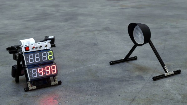
Once you have a track and a kart to race on it, what’s missing? A lap counter that can give your lap times in hardcopy, obviously! That’s what led [the_anykey] to create the Arduino-based Lap Timer to help him and his kids trim those precious seconds off their runs, complete with thermal printer for the results.

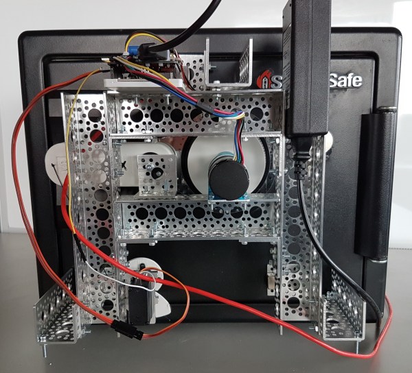
The hardware uses an infrared break-beam sensor module (a Velleman PEM10D) to detect when a kart passes by. This module is similar to a scaled-up IR reflective object sensor; it combines an IR emitter and receiver on one end, and is pointed at a reflector placed across the track, up to 10 meters away. When a kart breaks the beam, the module reports the event to the rest of the hardware. Only needing electronics on one side allows the unit to be self-contained.

An obvious shortcoming of this system is the inability to differentiate between multiple karts, but for timing a single driver’s performance it does the trick. What’s great about this project is it showcases how accessible hardware is today; a device like this is possible to put together with what are essentially off-the-shelf components available to any hobbyist, using an Arduino as the glue to hold it together. We’d only comment that a red-tinted piece of plastic as an overlay for the red display (and a grey-tinted one for the green) would make the LED displays much easier to read. Still, this is a very clean and well-documented build. See it in action in the video embedded below.

Continue reading “Reflective Sensor Becomes Kart Racing Lap Counter”

Safe Cracking Is [Nate’s] Latest R&D Project

We love taking on new and awesome builds, but finding that second part (the “awesome”) of each project is usually the challenge. Looks like [Nathan Seidle] is making awesome the focus of the R&D push he’s driving at Sparkfun. They just put up this safe cracking project which includes a little gamification.

The origin story of the safe itself is excellent. [Nate’s] wife picked it up on Craig’s List cheap since the previous owner had forgotten the combination. We’ve seen enough reddit/imgur threads to not care at all what’s inside of it, but we’re all about cracking the code.

The SparkX (the new rapid prototyping endeavor at Sparkfun) approach was to design an Arduino safe cracking shield. It has a motor driver for spinning the dial and can drive a servo that pulls the lever to open the door. There is a piezo buzzer to indicate success, and the board as a display header labeled but not in use, presumably to show the combination currently under test. We say “presumably” because they’re not publishing all the details until after it’s cracked, a process that will be live streamed starting Wednesday. This will keep us guessing on the use of that INA169 current sensor that plugs into the safecracking shield. There is what appears to be a reflectance sensor above the dial to keep precise track of the spinning dial.

Electrically this is what we’d expect, but mechanically we’re in love with the build. The dial and lever both have 3D printed adapters to interface with the rest of the system. The overall framework is built out of aluminum channel which is affixed to the safe with rare earth magnets — a very slick application of this gear.

The gamification of the project has to do with a pair of $100 giveaways they’re doing for the closest guess on how long it’ll take to crack (we hope it’s a fairly fast cracker) and what the actual combination may be. For now, we want to hear from you on two things. First, what is the role of that current sensor in the circuit? Second, is there a good trick for optimizing a brute force approach like this? We’ve seen mechanical peculiarities of Master locks exploited for fast cracking. But for this, we’re more interested in hearing any mathematical tricks to test likely combinations first. Sound off in the comments below

SparkFun Gets Back To Their Roots With SparkX

Way back in the before years when there were still interesting concepts for reality TV, Nate Seidle blew up a power supply in his dorm room. Instead of finding replacement parts, Nate decided to start a company. For the last decade and a half, SparkFun has grown immensely, been an incredible resource for makers and engineers alike, and shipped out hundreds of thousands of their iconic red boxes.

Being the CEO of a company means you need to do CEO stuff, and a few summers ago Nate the CEO became Nate the Engineer once again. SparkFun is still doing great, but now we know what Nate has been up to these last months. He’s getting back to SparkFun’s roots with SparkX. This is the newest stuff SparkFun has to offer, there is zero documentation or support, and they’re only developing products because Nate wants to.

In a series of blog posts on the SparkFun blog, Nate goes over what is involved in building a new brand for the latest and greatest SparkFun can produce. This involves setting up the SparkX lab, getting the OtherMills pumping out circuit boards, and  inevitably the occasional containment failure of the blue smoke.

The first product in the SparkX lineup, Product 0, is a breakout board for the MLX90393 magnetometer. This is a pretty nifty magnetometer that Ted Yapo over on hackaday.io has used to characterize magnets. Really, though, the SparkX Product 0 is exactly what it says on the tin: a breakout board that is just an experiment, comes with no guarantees or support. It is the heart of what Sparkfun set out to do twenty years ago.

Cornell Students Have Your Back

Back problems are some of the most common injuries among office workers and other jobs of a white-collar nature. These are injuries that develop over a long period of time and are often caused by poor posture or bad ergonomics. Some of the electrical engineering students at Cornell recognized this problem and used their senior design project to address this issue. [Rohit Jha], [Amanda Pustis], and [Erissa Irani] designed and built a posture correcting device that alerts the wearer whenever their spine isn’t in the ideal position.

The device fits into a tight-fitting shirt. The sensor itself is a flex sensor from Sparkfun which can detect deflections. This data is then read by a PIC32 microcontroller. Feedback for the wearer is done by a vibration motor and a TFT display with a push button. Of course, they didn’t just wire everything up and call it a day; there was a lot of biology research that went into this. The students worked to determine the most ideal posture for a typical person, the best place to put the sensor, and the best type of feedback to send out for a comfortable user experience.

We’re always excited to see the senior design projects from university students. They often push the boundaries of conventional thinking, and that’s exactly the skill that next generation of engineers will need. Be sure to check out the video of the project below, and if you want to see more of this semester’s other projects, we have you covered there tooContinue reading “Cornell Students Have Your Back”

The Mystery Behind The Globs Of Epoxy

When Sparkfun visited the factory that makes their multimeters and photographed a mysterious industrial process.

We all know that the little black globs on electronics has a semiconductor of some sort hiding beneath, but the process is one that’s not really explored much in the home shop.  The basic story being that, for various reasons , there is no cheaper way to get a chip on a board than to use the aptly named chip-on-board or COB process. Without the expense of encapsulating  the raw chunk of etched and plated silicon, the semiconductor retailer can sell the chip for pennies. It’s also a great way to accept delivery of custom silicon or place a grouping of chips closely together while maintaining a cheap, reliable, and low-profile package.

As SparkFun reveals, the story begins with a tray of silicon wafers. A person epoxies the wafer with some conductive glue to its place on the board. Surprisingly, alignment isn’t critical. The epoxy dries and then the circuit board is taken to a, “semi-automatic thermosonic wire bonding machine,” and slotted into a fixture at its base. The awesomely named machine needs the operator to find the center of the first two pads to be bonded with wire. Using this information it quickly bonds the pads on the silicon wafer to the  board — a process you’ll find satisfying in the clip below.

The final step is to place the familiar black blob of epoxy over the assembly and bake the board at the temperature the recipe in the datasheet demands. It’s a common manufacturing process that saves more money than coloring a multimeter anything other than yellow.

Continue reading “The Mystery Behind The Globs Of Epoxy”

Sparkfun Tears Apart Power Supplies

We love a good tear-down, and last week’s “Enginursday” at Sparkfun satisfied our desire to see the insides of AC-DC switching power supplies, accompanied by knowledgeable commentary. [MTaylor] walks us through how the basic circuit works and then points out why various other elaborations are made, and how corners are sometimes cut, in a few power supplies that he’s taken apart.

lishin_bottomshieldedWhat struck us in the comparison was that some of the power supplies were very minimal designs, while others had “features” that were obviously added after the fact. For instance, the Li Shin supply (about half-way down the page) has an extra circuit board tacked on to the bottom of the real circuit board to act as EM shielding.

Rather than declare this a dodgy hack, as we would have, [MTaylor] declares it to be “Good News!” because it means that they’ve probably run an emissions test, failed it, and then added this bit on to make it pass. This is of course in contrast to the other makers who’ve probably never even considered emissions testing. Sigh.

If you’re interested in seeing more inner bits of power bricks, Sparkfun forum reader [sgrace] passed along this field guide to various power supplies, which is also worth a look. And if you’re interested in building yourself the ultimate bench power supply, look no further than this Hackaday.io project by [The Big One].

Fight Frost With An Internet Of Things Fridge Alarm

It has been incredibly humid around these parts over the last week, and there seems to be something about these dog days that makes you leave the fridge or freezer door open by mistake. [pnjensen] found this happening all too often to the family chill chest, with the predictable accretion of frost on the coils as the water vapor condensed out of the entrained humid air and froze. The WiFi-enabled fridge alarm he built to fight this is a pretty neat hack with lots of potential for expansion.

Based on a Sparkfun ESP8266 Thing and home-brew door sensors built from copper tape, the alarm is rigged to sound after 120 seconds of the door being open. From the description it seems like the on-board buzzer provides a periodic reminder pip while the door is open before going into constant alarm and sending an SMS message or email; that’s a nice touch, and having the local alarm in addition to the text or email is good practice. As a bonus, [pjensen] also gets a log of each opening and closing of the fridge and freezer. As for expansion, the I2C header is just waiting for more sensors to be added, and the built-in LiPo charger would provide redundancy in a power failure.

If frost buildup is less a problem for you than midnight snack runs causing another kind of buildup, you might want to check out this willpower-enhancing IoT fridge alarm.