Playing the guitar requires speed, strength, and dexterity in both hands. Depending on your mobility level, rocking out with your axe might be impossible unless you could somehow hold down the strings and have a robot do the strumming for you.
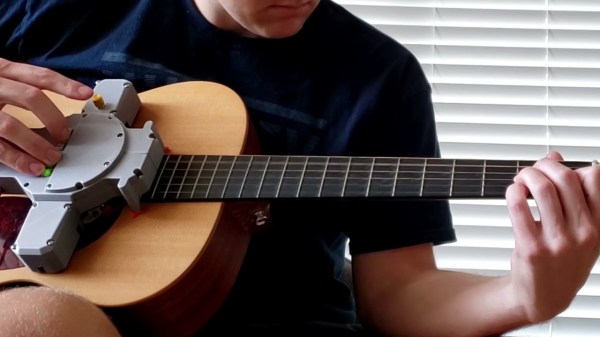
 [Jacob Stambaugh]’s Auto Strummer uses six lighted buttons to tell the hidden internal pick which string(s) to strum, which it does with the help of an Arduino Pro Mini and a stepper motor. If two or more buttons are pressed, all the strings between the outermost pair selected will be strummed. That little golden knob near the top is a pot that controls the strumming tempo.
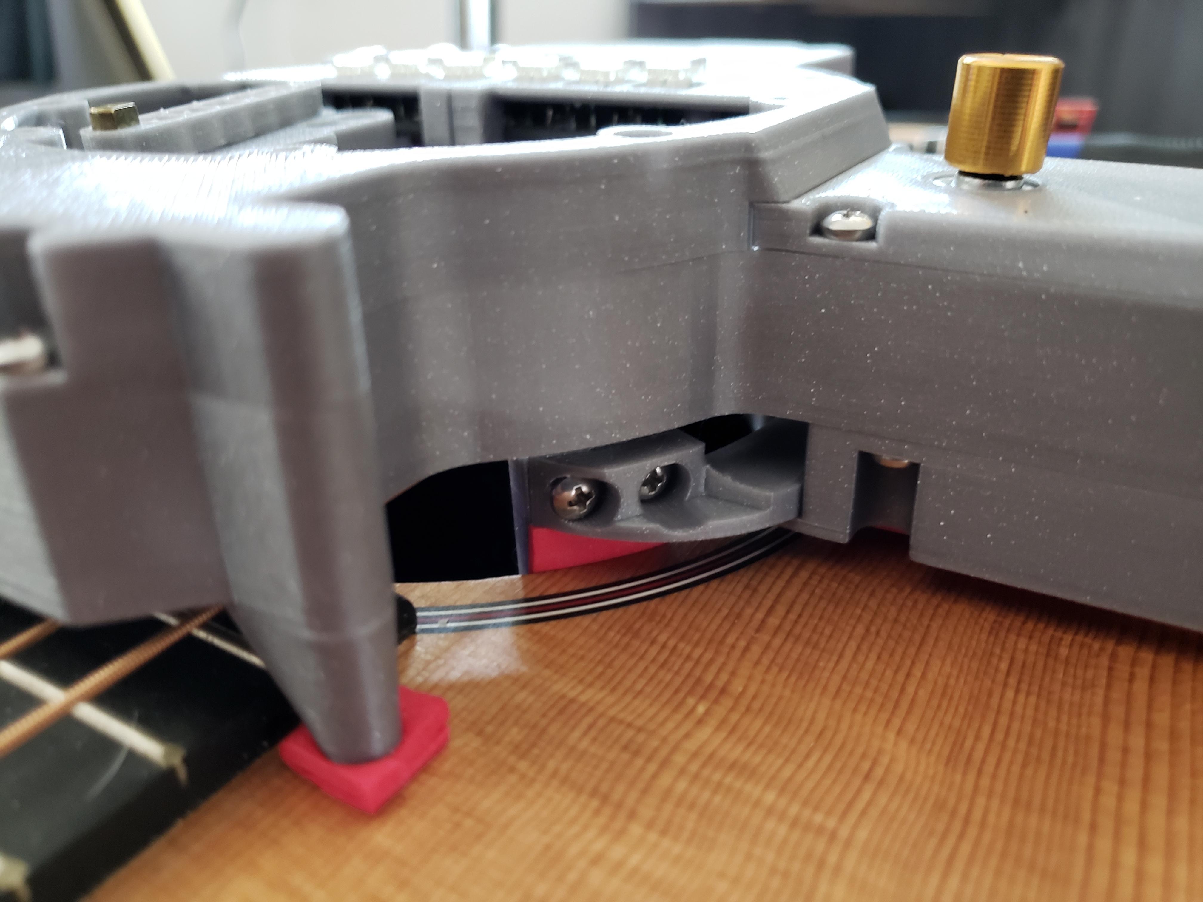
[Jacob]’s impressive 3D-printed enclosure attaches to the guitar with a pair of spring-loaded clamps that grasp the edge of the sound hole. But don’t fret — there’s plenty of foam padding under every point that touches the soundboard.
We were worried that the enclosure would block or muffle the sound, even though it sits about an inch above the hole. But as you can hear in the video after the break, that doesn’t seem to be the case — it sounds fantastic.
Never touched a real guitar, but love to play Guitar Hero? There’s a robot for that, too.
Continue reading “Auto Strummer Can Plectrum The Whole Flat-Strumming Spectrum”