Behold A Geared, Continuously Variable Transmission

When it comes to transmissions, a geared continuously-variable transmission (CVT) is a bit of a holy grail. CVTs allow smooth on-the-fly adjustment of gear ratios to maintain a target speed or power requirement, but sacrifice transmission efficiency in the process. Geared transmissions are more efficient, but shift gear ratios only in discrete steps. A geared CVT would hit all the bases, but most CVTs are belt drives. What would a geared one even look like? No need to wonder, you can see one for yourself. Don’t miss the two videos embedded below the page break.

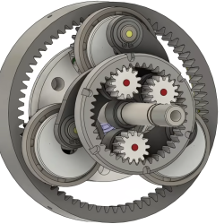
The outer ring is the input, the inner ring is the output, and the three little gears with dots take turns transferring power.

The design is called the RatioZero and it’s reminiscent of a planetary gearbox, but with some changes. Here’s how the most visible part works: the outer ring is the input and the inner ring is the output. The three small gears inside the inner ring work a bit like relay runners in that each one takes a turn transferring power before “handing off” to the next. The end result is a smooth, stepless adjustment of gear ratios with the best of both worlds. Toothed gears maximize transmission efficiency while the continuously-variable gear ratio allows maximizing engine efficiency.

There are plenty of animations of how the system works but we think the clearest demonstration comes from [driving 4 answers] with a video of a prototype, which is embedded below. It’s a great video, and the demo begins at 8:54 if you want to skip straight to that part.

One may think of motors and gearboxes are a solved problem since they have been around for so long, but the opportunities to improve are ongoing and numerous. Even EV motors have a lot of room for improvement, chief among them being breaking up with rare earth elements while maintaining performance and efficiency.

Continue reading “Behold A Geared, Continuously Variable Transmission”

Retrotechtacular: Powerline Sagging And Stringing In The 1950s

While high-voltage transmission lines are probably the most visible components of the electrical grid, they’re certainly among the least appreciated. They go largely unnoticed by the general public — quick, name the power line closest to you right now — at least until a new one is proposed, causing the NIMBYs and BANANAs to come out in force. To add insult to injury, those who do notice the megastructures that make modern life possible rarely take a moment to appreciate the engineering that goes into stringing up hundreds of miles of cable and making sure it stays up.

Not so the Bonneville Power Administration, the New Deal-era federal agency formed to exploit the hydroelectric abundance of the Pacific Northwest of the United States, which produced this 1950 gem detailing the stringing and sagging of power lines. Unsurprisingly, the many projects needed to wire together the often remote dams to the widely distributed population centers in an area that was only just starting to see growth began in the BPA’s offices, where teams of engineers hunched over desks worked out the best routes. Paper, pencil, and slide rules were the tools of the trade, along with an interesting gadget called a conductor sag template, a hardware implementation of the catenary equation that allowed the “sagger” to determine the height of each tower. The conductors, either steel-cored aluminum or pure copper, were also meticulously selected based on tensile strength, expected wind and ice loading, and the electrical load the line was expected to carry.

Once the engineers had their say, the hard work of physically stringing the wires began out in the field. One suspects that the work today is much the same as it was almost eighty years ago, save for much more stringent health and safety regulations. The prowess needed to transfer the wires from lifting sheaves to the insulators is something to behold, and the courage required to work from ladders hanging from wires at certain death heights is something to behold. But to our mind, the real heroes were the logistics fellows, who determined how much wire was needed for each span and exactly where to stage the reels. It’s worth sparing a moment’s thought for the daring photographer who captured all this action, likely with little more than a leather belt and hemp rope for safety.

Continue reading “Retrotechtacular: Powerline Sagging And Stringing In The 1950s”

This Go-Kart Rides On A Pallet

Many beginner woodworkers, looking to offset the introductory costs of starting a hobby, will source their wood from pallets. Generally they’re easily found and can be low or no cost, but typically require a bit of work before they’re usable in a project. [Garage Avenger] is looking to do something a little outside of the box with his pallet project, though. He’s using raw pallets as a chassis for a four-speed go-kart, partially for the challenge and excitement and also to one-up a Pinterest post.

Almost immediately, though, the other major downside of working with pallets arose which is that they’re generally built out of low-grade pine which is soft and flexible. Flexibility is generally not a good thing to have in a vehicle frame so plenty of the important parts of this build were strengthened with steel tubing including the rear axle, steering mounts, and a few longitudinal supports to strengthen the overall frame. After working out some kinks with ordering a few of the wrong parts, and mounting the steering box backwards, it was time to test out the four-speed engine (and brakes) on the the go-kart, making it nearly ready for the road.

To complete the build, some tidying of wiring and fuel lines was done, along with improving some of the non-critical parts of the build like the bucket seat. Of course, adding pallet spoilers and body kit puts the finishing touches on the build and the go-kart is finally ready to tear up the local go-kart track and the less-inspiring Pinterest projects. [Garage Avenger] is no stranger to strange vehicle builds, either. Although it’s a bit out of season for most of our northern hemisphere readers now, his jet-powered street sled is still worth a view.

Continue reading “This Go-Kart Rides On A Pallet”

A CVT For Every Application

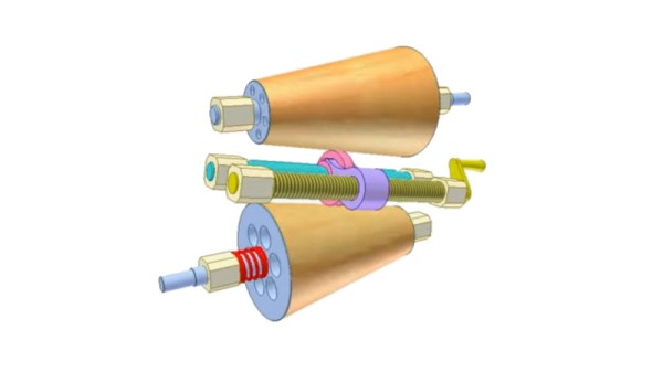
When the subject of CVTs or continuously variable transmissions comes up, the chances are that most readers will think of the various motor vehicles they’ve appeared in. Whether it’s a DAF, a Ford, a FIAT, or a Chevrolet, most major manufacturers have tried one at some point or another with greater or lesser success. The automotive ones inevitably use a variation on a V-belt or metal band between variable separation conical pulleys, but this is by no means the only CVT configuration. Serial tinkerer [Robert Murray-Smith] takes an in-depth look at the subject as part of his ongoing fascination with wind turbines.

What caught our eye about this video isn’t so much the final 3D-printed design he selects for his experiments, but the history and his look at the different CVT designs which have appeared over the years. We see the V-belts, as well as the various cone configurations, the disk transmissions, the hydrostatic ones, and even magnetic versions. His transmission uses two cones with a rubber coating, with of all things a movable golf ball between them. We’re guessing it will appear somewhere in his future videos, so watch out for it.

Meanwhile, this isn’t the first time we’ve seen a CVT, [James Bruton] used a hemisphere to make one on a robot.

Continue reading “A CVT For Every Application”

Clever Mechanism Powers This All-Mechanical Filament Respooler

No matter how far down the 3D printing rabbit hole we descend, chances are pretty good that most of us won’t ever need to move filament from one spool to another. But even so, you’ve got to respect this purely mechanical filament respooler design, and you may want to build one for yourself just because.

We were tipped off to [Miklos Kiszely]’s respooler via the very enthusiastic video below from [Bryan Vines] at the BV3D YouTube channel. He explains the need for transferring filament to another spool as stemming from the switch by some filament manufacturers to cardboard spools for environmental reasons. Sadly, these spools tend to shed fibrous debris that can clog mechanisms; transferring filament to a plastic spool can help mitigate that problem.

The engineering that [Miklos] put into his respooler design is pretty amazing. Bearings excepted, the whole thing is 3D printed. A transmission made of herringbone gears powers both the take-up spool and the filament guide, which moves the incoming filament across the width of the spool for even layers. The mechanism to do this is fascinating, consisting of a sector gear with racks on either side. The racks are alternately engaged by the sector gear, moving a PTFE filament guide tube back and forth to create even layers on the takeup spool. Genius!

Hats off to [Miklos] on this clever design, and for the extremely detailed instructions for printing and building one of your own. Even if you don’t have the cardboard problem, maybe this would help if you buy filament on really big spools and need to rewind for printing. Continue reading “Clever Mechanism Powers This All-Mechanical Filament Respooler”

Replace Your Automatic Transmission With A Bunch Of Relays

A “Check Engine” light on your dashboard could mean anything from a loose gas cap to a wallet-destroying repair in the offing. For [Dean Segovis], his CEL was indicating a fairly serious condition: a missing transmission. So naturally, he built this electronic transmission emulator to solve the problem.

Some explanation may be necessary here. [Dean]’s missing transmission was the result of neither theft nor accident. Rather, he replaced the failed automatic transmission on his 2003 Volkswagen EuroVan with a manual transmission. Trouble is, that left the car’s computer convinced that the many solenoids and sensors on the original transmission weren’t working, leaving him with a perfectly serviceable vehicle but an inspection-failing light on the dash.

To convince the transmission control module that a working automatic was still installed and clear the fourteen-odd diagnostic codes, [Dean] put together a block of eight common automotive relays. The relay coils approximate the resistance of the original transmission’s actuators, which convinces the TCU that everything is hunky dory. There were also a couple of speed sensors in the transmission, which he spoofed with some resistors, as well as the multi-function switch, which detects the shift lever position. All told, the emulator convinces the TCU that there’s an automatic transmission installed, which is enough for it to give the all-clear and turn off the Check Engine light on the dash.

We love hacks like this, and hats off to [Dean] for sharing it with the VW community. Apparently the issue with the EuroVan automatic transmissions is common enough that a cottage industry has developed to replace them with manuals. It’s not the only questionable aspect of VW engineering, of course, but this could help quite a few people out of a sticky situation.

Continue reading “Replace Your Automatic Transmission With A Bunch Of Relays”

Homebrew Optical Sensor Helps Your Diesel Pass The Smoke Test

We’ve all heard of the smoke test, and we know that it’s the lowest possible bar for performance of an electronic device. If it doesn’t burst into flames when power is applied, you’re good to go for more functional testing. But the smoke test means something else for cars, especially those powered by diesel fuel. And passing diesel exhaust tests can become something of a chore.

To make passing these tests a little easier, [Janis Alnis] came up with this diesel exhaust monitor that measures the opacity of his car’s emissions. The sensor itself is quite simple, and mimics what commercial exhaust analyzers use: a LED and a photodiode at opposite ends of a tube of a specified length. Soot particles in exhaust passing through the tube will scatter light in a predictable way, and the numbers work out that a passing grade is anything greater than 53% transmission.

The sensor body is cobbled together from brass pipe fittings with glass windows epoxied into each end. Exhaust enters via a tee fitting attached to a hose and sampling tube, and exits through another tee. One window of the sensor has a cheap battery-powered flashlight as a light source, while the other end has a Texas Instruments OPT101 photodiode sensor. The sensor is connected to one of the analog inputs of an Arduino, which also runs a 128×64 pixel LCD display — inspired by this air quality meter — to show the current smokiness both graphically and as a percentage. The video below shows the sensor at work.

While there were some issues with soot buildup and water vapor condensation, using the sensor [Janis] discovered that a little bit of a warm-up drive got things hot enough to clear up his ride’s tendency to smoke a bit, allowing him to pass his inspection. Continue reading “Homebrew Optical Sensor Helps Your Diesel Pass The Smoke Test”