Where Do You Connect The Shield?

When it comes to polarizing and confusing questions in electronics, wiring up shields is on the top-10 list when sorted by popularity. It’s a question most of us need to figure out at some point – when you place a USB socket symbol on your schematic, where do you wire up the SHIELD and MP pins?

Once you look it up, you will find Eevblog forum threads with dozens of conflicting replies, Stackexchange posts with seven different responses plus a few downvoted ones, none of them accepted, and if you try to consult the literature, the answer will invariably be “it depends”.

I’m not a connector-ground expert, I just do a fair bit of both reading and hacking. Still, I’ve been trying to figure out this debate, for a couple years now, re-reading the forum posts each time I started a new schematic with a yet-unfamiliar connector. Now, of course, coming to this question with my own bias, here’s a summary you can fall back on.

Consumer Ports

Putting HDMI on your board? First of all, good luck. Then, consider – do you have a reason to avoid connecting the shield? If not, certainly connect the shield to ground, use jumpers if that’s what makes you comfortable, though there’s a good argument that you should just connect directly, too. The reason is simple: a fair few HDMI cables omit GND pin connections, fully relying on the shield for return currents. When your HDMI connection misfires, you don’t want to be debugging your HDMI transmitter settings when the actual No Signal problem, as unintuitive as it sounds, will be simply your shield not being grounded – like BeagleBone and Odroid didn’t in the early days. By the way, is a DVI-D to HDMI adapter not working for you? Well, it might just be that it’s built in a cheap way and doesn’t connect the shields of the two sockets together – which is fixable.

Continue reading “Where Do You Connect The Shield?”

Rescuing High-Res Displays From Older Macs

When Apple started rolling out its Retina displays, it multiplied the amount of pixels compared to their standard, non-Retina displays by four. This increased pixel density while keeping the standard screen size — idea for those needing a lot of detail for their work. But, as is common with Apple, using these displays outside of the Apple ecosystem can be quite a challenge. Retina displays have been around for about a decade now, though, with some third-party hardware able to break them free of their cage. This post details how [Kevin] liberated the 5K display from a 2017 iMac for more general use with support for USB-C.

The first step was to find a used iMac for the right price, and then sell off most of its parts to recoup most of the initial cost. That brought the cost of the panel itself to about $250. The key to getting the display working without all of the Apple hardware is the R1811 driver board, which can be had for around $300. A new 156 watt power supply was added to the mix, and [Kevin] also put in a few extras like a USB cable extension and a latching push-button which kills the display’s power. Additionally, he attempted to get the original iMac speakers working with this setup too, but none of his attempts resulted in anything close to quality sound so he’s mostly abandoned that extra feature for now.

With that all buttoned up, he has a 27″ 5K display with USB-C input for around $650 which is quite a deal. The MacRumors thread that [Kevin] added his project to currently has around 1,700 posts about similar builds too, so it can be a wealth of information for all kinds of models. As Apple drops support for their older machines, these displays will become more and more common and projects like these can keep a lot of e-waste out of the landfill while also providing decent hardware at a bargain price. Don’t just look for iMacs and MacBooks though; there’s a similar process to use various iPad displays for other things as well.

Universal Power Bank Customized To Your Liking

One of the most troubling trends of almost every modern consumer product that uses electricity is that the software that controls the product is likely to be proprietary and closed-source, which could be doing (or not doing) any number of things that its owner has no control over. Whether it’s a computer, kitchen appliance, or even a device that handles the electricity directly, it’s fairly rare to find something with software that’s open and customizable. That’s why [Traditional-Code9728] is working on a power bank with an open-source firmware.

From a hardware perspective the power bank is fairly open as well, with a number of options for connecting this device to anything else that might need power. It sports a bidirectional USB-C port as well as a DC barrel plug, either of which can either charge other devices or receive energy to charge its own battery. These ports can also accept energy from a solar panel and have MPPT built in. There’s also dual USB-A ports which can provide anywhere from five to 12 volts at 25 watts, and a color screen which shows the current status of the device.

While this is a prototype device, it’s still actively being worked on. Some future planned upgrades to the power bank include a slimmer design, charge limiting features to improve battery life, and more fine-tuned control of the output voltage and current on the USB-C port. With all of the software being open-source, as well as the circuit diagram and 3D printing files, it could find itself in plenty of applications as well. This power bank also stays under the energy limits for flying on most commercial airlines as well, but if you don’t plan on taking your power bank on an airplane then you might want to try out this 2000-watt monster instead.

USB And The Myth Of 500 Milliamps

If you’re designing a universal port, you will be expected to provide power. This was a lesson learned in the times of LPT and COM ports, where factory-made peripherals and DIY boards alike had to pull peculiar tricks to get a few milliamps, often tapping data lines. Do it wrong, and a port will burn up – in the best case, it’ll be your port, in worst case, ports of a number of your customers.

Want a single-cable device on a COM port? You might end up doing something like this.

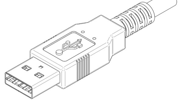
Having a dedicated power rail on your connector simply solves this problem. We might’ve never gotten DB-11 and DB-27, but we did eventually get USB, with one of its four pins dedicated to a 5 V power rail. I vividly remember seeing my first USB port, on the side of a Thinkpad 390E that my dad bought in 2000s – I was eight years old at the time. It was merely USB 1.0, and yet, while I never got to properly make use of that port, it definitely marked the beginning of my USB adventures.

About six years later, I was sitting at my desk, trying to build a USB docking station for my EEE PC, as I was hoping, with tons of peripherals inside. Shorting out the USB port due to faulty connections or too many devices connected at once was a regular occurrence; thankfully, the laptop persevered as much as I did. Trying to do some research, one thing I kept stumbling upon was the 500 mA limit. That didn’t really help, since none of the devices I used even attempted to indicate their power consumption on the package – you would get a USB hub saying “100 mA” or a mouse saying “500 mA” with nary an elaboration.

Fifteen more years have passed, and I am here, having gone through hundreds of laptop schematics, investigated and learned from design decisions, harvested laptops for both parts and even ICs on their motherboards, designed and built laptop mods, nowadays I’m even designing my own laptop motherboards! If you ever read about the 500 mA limit and thought of it as a constraint for your project, worry not – it’s not as cut and dried as the specification might have you believe.
Continue reading “USB And The Myth Of 500 Milliamps”

Hackaday Links Column Banner

Hackaday Links: June 16, 2024

Attention, slackers — if you do remote work for a financial institution, using a mouse jiggler might not be the best career move. That’s what a dozen people learned this week as they became former employees of Wells Fargo after allegedly being caught “simulating keyboard activity” while working remotely. Having now spent more than twice as many years working either hybrid or fully remote, we get it; sometimes, you’ve just got to step away from the keyboard for a bit. But we’ve never once felt the need to create the “impression of active work” during those absences. Perhaps that’s because we’ve never worked in a regulated environment like financial services.

For our part, we’re curious as to how the bank detected the use of a jiggler. The linked article mentions that regulators recently tightened rules that require employers to treat an employee’s home as a “non-branch location” subject to periodic inspection. More than enough reason to quit, in our opinion, but perhaps they sent someone snooping? More likely, the activity simulators were discovered by technical means. The article contains a helpful tip to avoid powering a jiggler from the computer’s USB, which implies detecting the device over the port. Our guess is that Wells tracks mouse and keyboard activity and compares it against a machine-learning model to look for signs of slacking.

Continue reading “Hackaday Links: June 16, 2024”

USB Dongle Brings Python-Controlled GPIO To The Desktop

Microcontroller dev boards are wonderfully useful items, in testament to which most of us maintain an ample collection of the things. But dragging one out to do a simple job can be a pain, what with making sure you have the whole toolchain set up to support the device, not to mention the inevitable need to solder or desolder header pins. Wouldn’t it be nice if there was a simple plug-and-play way to add a few bits of GPIO to your desktop or laptop machine?

[Nick Bild] thinks so, and came up with the USBgpio. The hardware in the dongle is pretty much what you’d expect — an Arduino Nano 33 IoT. Yes, you could just bust out a Nano and do this yourself, but [Nick] has done all the heavy lifting already. Eleven of the Nano’s IO pins plus 3.3V and ground are broken out to header pins that stick out of the 3D-printed enclosure, and the dongle is powered over the USB cable. [Nick] also built a Python library for the USBgpio, making it easy to whip up a quick program. You just import the library, define the serial port and baud rate, and the library takes care of the rest. The video below shows a quick blinkenlight test app.

Earth-shattering stuff? Perhaps not; [Nick] admits as much by noting the performance doesn’t really dazzle. But that’s hardly the point of the project, and if you need a couple of pins of IO on the desktop for a quick tactical project or some early-stage prototyping, USBgpio could be your friend. Continue reading “USB Dongle Brings Python-Controlled GPIO To The Desktop”

2024 Business Card Challenge: Adding Some Refinement To Breadboard Power Supplies

For small electronics projects, prototyping a design on a breadboard is a must to iron out kinks in the design and ensure everything works properly before a final version is created. The power supply for the breadboard is often overlooked, with newcomers to electronics sometimes using a 9V battery and regulator or a cheap USB supply to get a quick 5V source. We might eventually move on to hacking together an ATX power supply, or the more affluent among us might spring for a variable, regulated bench supply, but this power supply built specifically for breadboards might thread the needle for this use case much better than other options.

The unique supply is hosted on a small PCB with two breakout rails that connect directly to the positive and negative pins on a standard-sized breadboard. The power supply has two outputs, each of which can output up to 24V DC and both are adjustable by potentiometers. To maintain high efficiency and lower component sizes, a switch-mode design is used to provide variable DC voltage. A three-digit, seven-segment display at the top of the board keeps track of whichever output the user selects, and the supply itself can be powered by a number of inputs, including USB-C or lithium batteries.

Continue reading “2024 Business Card Challenge: Adding Some Refinement To Breadboard Power Supplies”