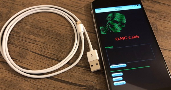
If you weren’t scared of USB cables before, you should be now. The O.MG cable (or Offensive MG kit) from [MG] hides a backdoor inside the shell of a USB connector. Plug this cable into your computer and you’ll be the victim of remote attacks over WiFi.
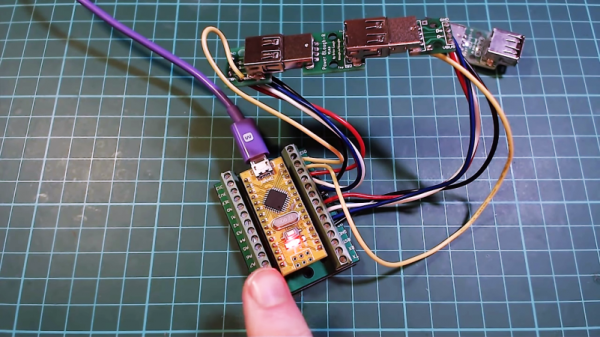
You might be asking what’s inside this tiny USB cable to make it susceptible to such attacks. That’s the trick: inside the shell of the USB ‘A’ connector is a PCB loaded up with a WiFi microcontroller — the documentation doesn’t say which one — that will send payloads over the USB device. Think of it as a BadUSB device, like the USB Rubber Ducky from Hak5, but one that you can remote control. It is the ultimate way into a system, and all anyone has to do is plug a random USB cable into their computer.
In the years BadUSB — an exploit hidden in a device’s USB controller itself — was released upon the world, [MG] has been tirelessly working on making his own malicious USB device, and now it’s finally ready. The O.MG cable hides a backdoor inside the shell of a standard, off-the-shelf USB cable.
The construction of this device is quite impressive, in that it fits entirely inside a USB plug. But this isn’t a just a PCB from a random Chinese board house: [MG] spend 300 hours and $4000 in the last month putting this project together with a Bantam mill and created his own PCBs, with silk screen. That’s impressive no matter how you cut it.
Future updates to this cable that will hack any computer might include a port of ESPloitV2, an Open Source WiFi controlled USB HID keyboard emulator. That will bring a lot of power to this device that’s already extremely capable. In the video attached to this tweet you can see the O.MG cable connected to a MacBook, with [MG] opening up a webpage remotely.