Open Source IDE For FPGAs As QtCreator Learns Verilog

Classic battles: PC vs Mac, Emacs vs Vi, Tastes Great vs Less Filling, and certainly one that we debate around the Hackaday watercooler: command line or IDE? There’s something to be said for using good old command line tools, and even if you like to configure your favorite editor to be nearly an IDE, at least it is one you are familiar with and presumably leverage over several different uses.

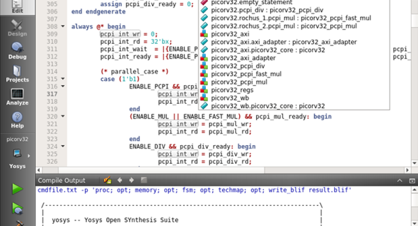
Most commercial FPGA tools come with a heavy-weight IDE. The open source tools for Lattice (IceStorm) typically is driven by the command line or a makefile. Until now. [Rochus-Keller] released VerilogCreator which is a plugin for QtCreator.

We were impressed because as IDEs go, QtCreator is both useful and lightweight, two things that don’t go together for many similar tools. [FPGAwars] has had an IDE based on Atom (apio-ide) although it hasn’t been updated in nearly a year. IceStudio sees more updates, of course, but it isn’t so much an IDE as a GUI-based code builder.

[Rochus-Keller] says there’s more to come. However, even at this early stage the IDE does syntax coloring, tooltips, inline messages, and can analyze source code allowing you to cross-reference symbols as you’d expect. There are configurations for Icarus to do simulations or you can use Verilator or Yosys — the synthesizer behind IceStorm. It appears it can also interact with Tcl-based workflows like those used by most FPGA vendor IDEs.

There’s quite a bit still on the to-do list, so we are excited to see where this is going. QtCreator isn’t hard to learn and it doesn’t’ feel as bloated as some of the big IDEs like Eclipse. If you want a quick introduction to QtCreator, we did that already. If you want to draw boxes instead of writing Verilog directly, try IceStudio.

Old Game Development IDE Goes FPGA

If you have a thing for old game development — things like the Atari 2600 or similar period arcade games — you might already know about the 8bitworkshop IDE. There you can develop code in your browser for those platforms. In a recent blog post, the site announced you can now also do FPGA development in the IDE.

According to the site:

Most computers are fast enough to render a game at 60 Hz, which requires simulating Verilog at almost 5 million ticks per second.

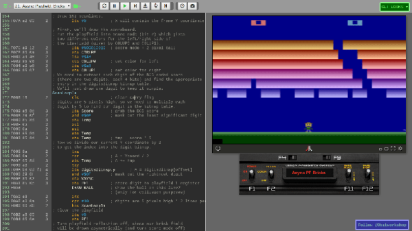
To activate Verilog, you need to select the hamburger menu to the top left, select Platform, and then under Hardware, check Verilog. What makes this different from, say, EDA Playground, is that the output can be waveforms or the output to a virtual TV monitor. For example, here’s one of the examples:

The Verilog code is generating horizontal and vertical sync along with an RGB output and the results appear on the monitor to the right. There is a handle at the bottom of the screen. If you drag it up you will see the logic analyzer output. Drag it down and you’ll see the screen again. The examples include an 8-bit and 16-bit CPU, and example games that can even read the mouse.

Honestly, we don’t think anyone would suggest using Verilog to write in-browser games. That isn’t really the point here. However, if you are trying to learn Verilog, it is great fun to be able to produce something other than just abstract waveforms from simulation. The only downside is that to move to a real piece of hardware, you’d need to duplicate the interfaces provided by the IDE. That would not be very hard, and — of course — if you are just using it to learn you can try a different project for the real world.

If you need help getting going in Verilog, we have a series of boot camps that can help. Those tutorials use EDA Playground, but they’d probably work here, too. If you try them in the IDE, be sure to let us know your experience.

FPGA Emulates A PDP-1, Breathes New Life Into Classic Video Game

If you’ve ever wanted to sit at the console of the machine that started the revolution in interactive computing, your options are extremely limited. Of the 53 PDP-1 machines that Digital Equipment Corporation made, only three are known to still exist, and just one machine is still in working order at the Computer History Museum. So a rousing game of Spacewar! on the original hardware is probably not something to put on your bucket list.

But thanks to [Hrvoje], there’s now an FPGA emulation of the PDP-1 that lets you play the granddaddy of all video games without breaking into the CHM. The project was started simply to give [Hrvoje] a sandbox for learning FPGAs and Verilog, but apparently went much further than that. The emulation features the complete PDP-1 instruction set, 4kB of core memory, and representations of the original paper tape reader, teletype, operator’s console, and the classic Type 30 CRT. All the hardware is displayed on a standard HDMI monitor, but it’s the CRT implementation that really sells this. The original Type 30 monitor used a CRT from a radar set, and had long-persistence phosphors that gave the display a very distinctive look. [Hrvoje] replicated that by storing each pixel as three values (X, Y, and brightness) in a circle of four chained shift registers. As the pixels move through the shift registers, the brightness value is decreased so it slowly fades. [Hrvoje] thinks it doesn’t look quite right, but we’ll respectfully disagree on that point.

We’ve argued before that the PDP-1 is the machine that started hacker culture, and we think this project is a fitting tribute to the machine as we enter the year in which it will turn sixty. Having the chance to play with it through this emulation is just icing on its birthday cake.

Continue reading “FPGA Emulates A PDP-1, Breathes New Life Into Classic Video Game”

VexRISC-V Exposed

If you want to use FPGAs, you’ll almost always use an HDL like Verilog or VHDL. These are layers of abstraction just like using, say, a C compiler is to machine language or assembly code. There are other challengers to the throne such as SpinalHDL which have small but enthusiastic followings. [Tom] has a post about how the VexRISC-V CPU leverages SpinalHDL to make an extremely flexible system that is as efficient as plain Verilog. He says the example really shows off why you should be using SpinaHDL.

Like a conventional programming language, it is easy to find niche languages that will attract a little attention and either take off (say, C++, Java, or Rust) or just sort of fade away. The problem is you can’t ever tell which ones are going to become major and which are just flashes in the pan. Is SpinalHDL the next big thing? We don’t know.

Continue reading “VexRISC-V Exposed”

Packing Decimal Numbers Easily

While desktop computers have tons of computing power and storage, some small CPUs don’t have a lot of space to store things. What’s more is some CPUs don’t do multiplication and division very well. Same can be said for FPGAs. So suppose we are going to grab a bunch of three-digit decimal numbers from, say, a serial port. We want to store as many as we can, and we don’t want to do a lot of math because we can’t, it is slow, or perhaps it keeps our processor awake longer and we want to sleep to conserve power. We want a way to pack the numbers as close to the theoretical maximum as we can but with little or no math.

The simple approach is to store the numbers as ASCII. Great for processing since they are probably in ASCII already. If they aren’t, you just add 30 hex to each digit and you are done. That’s awful for storage space, though, since we can store 999 in 10 bits if it were binary and now we are using 24 bits! Storing in binary isn’t a good option, if you play by our rules, by the way. You need to multiply by 10 and 100 (or 10 twice) to get the encoding. Granted, you can change that to two shifts and an add (8x+2x=10x) but there’s no easy way to do the division you’ll have to do for the decode.

Of course, there’s no reason we can’t just store decimal digits. That’s call binary coded decimal or BCD and that has some advantages, too. It is pretty easy to do math on BCD numbers and you don’t get rounding problems. Some CPUs even have specific instructions for BCD manipulation. However, three digits will require 12 bits. That’s better than 24, we agree. But it isn’t as good as that theoretical maximum. After all, if you think about it, you could store 16 distinct codes in 4 bits, and we are storing only 10, so that 6 positions lost. Multiply that by 3 and you are wasting 18 codes.

But there is a way to hit that ten-bit target without doing any math. Its called DPD or densely packed decimal. You can convert three decimal digits into ten bits and then back again with no real math at all. You could implement it with a small lookup table or just do some very simple multiplexer-style logic which means it is cheap and easy to implement in software or onboard an FPGA.

Continue reading “Packing Decimal Numbers Easily”

FPGA Testbenches Made Easier

You finally finish writing the Verilog for that amazing new DSP function that will revolutionize human society and make you rich. Does it work? Your first instinct, of course, is to blow it into your FPGA of choice and see if it works. If it does, that was a great idea. If it doesn’t, it was a terrible idea because — typically — it is hard to look inside the FPGA. That’s why you’ll typical simulate your logic on a desktop computer before you commit it to the FPGA. But that means you have to delay gratification long enough to write a testbench — a piece of hardware description language (HDL) code that exercises the function you wrote. In this post I’ll show you a small piece of software that can read your Verilog module and automatically create most of a testbench for you. The code originally came from GitHub, but I wanted to make some changes to it, so I forked it and I’ll tell you about the changes I made. This isn’t specific to a particular FPGA. Any Verilog project can use the tool to generate a simple starter testbench.

Writing a testbench isn’t that hard. You usually use the same language you wrote the original code in but since it won’t reside in silicon, you can do things in the simulator that you can’t get away with in code that you’ll synthesize. However, it is a bit painful to have to always write more or less the same code, especially if you have a lot of modules you want to test. But it is a good idea to test small modules before linking them together and then test them linked together, too. With this little Python script, it is very easy to generate a simple testbench and then further elaborate it. It isn’t life-changing, but it does save some time. If you want to try this out, you’ll need something to run the Python script on, of course. You also need a Verilog simulator or you can use EDA Playground to try all this out in your browser.

Continue reading “FPGA Testbenches Made Easier”

X-Ray Vision For FPGAs: Using Verifla

Last time I talked about how I took the open source Verifla logic analyzer and modified it to have some extra features. As promised, this time I want to show it in action, so you can incorporate it into your own designs. The original code didn’t actually capture your data. Instead, it created a Verilog simulation that would produce identical outputs to your FPGA. If you were trying to do some black box simulation, that probably makes sense. I just wanted to view data, so I created a simple C program that generates a VCD file you can read with common tools like gtkwave. It is all on GitHub along with the original files, even though some of those are not updated to match the new code (notably, the PDF document and the examples).

If you have enough pins, of course, you can use an external logic analyzer. If you have enough free space on the FPGA, you could put something like SUMP or SUMP2 in your design which would be very flexible. However, since these analyzers are made to be configurable from the host computer, they probably have a lot of circuitry that will compete with yours for FPGA space. You configure Verifla at compile time which is not as convenient but lets it have a smaller footprint.

Continue reading “X-Ray Vision For FPGAs: Using Verifla”