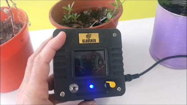
Looking for a digital recreation of the classic analog volume unit (VU) meter? If you’ve got an Arduino, a few passive components, and a SSD1306 OLED, then [mircemk] might have the answer for you. As you can see in the video below, his code turns a handful of cheap parts into an attractive and functional audio display.
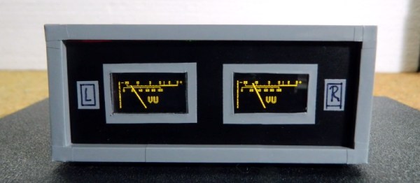
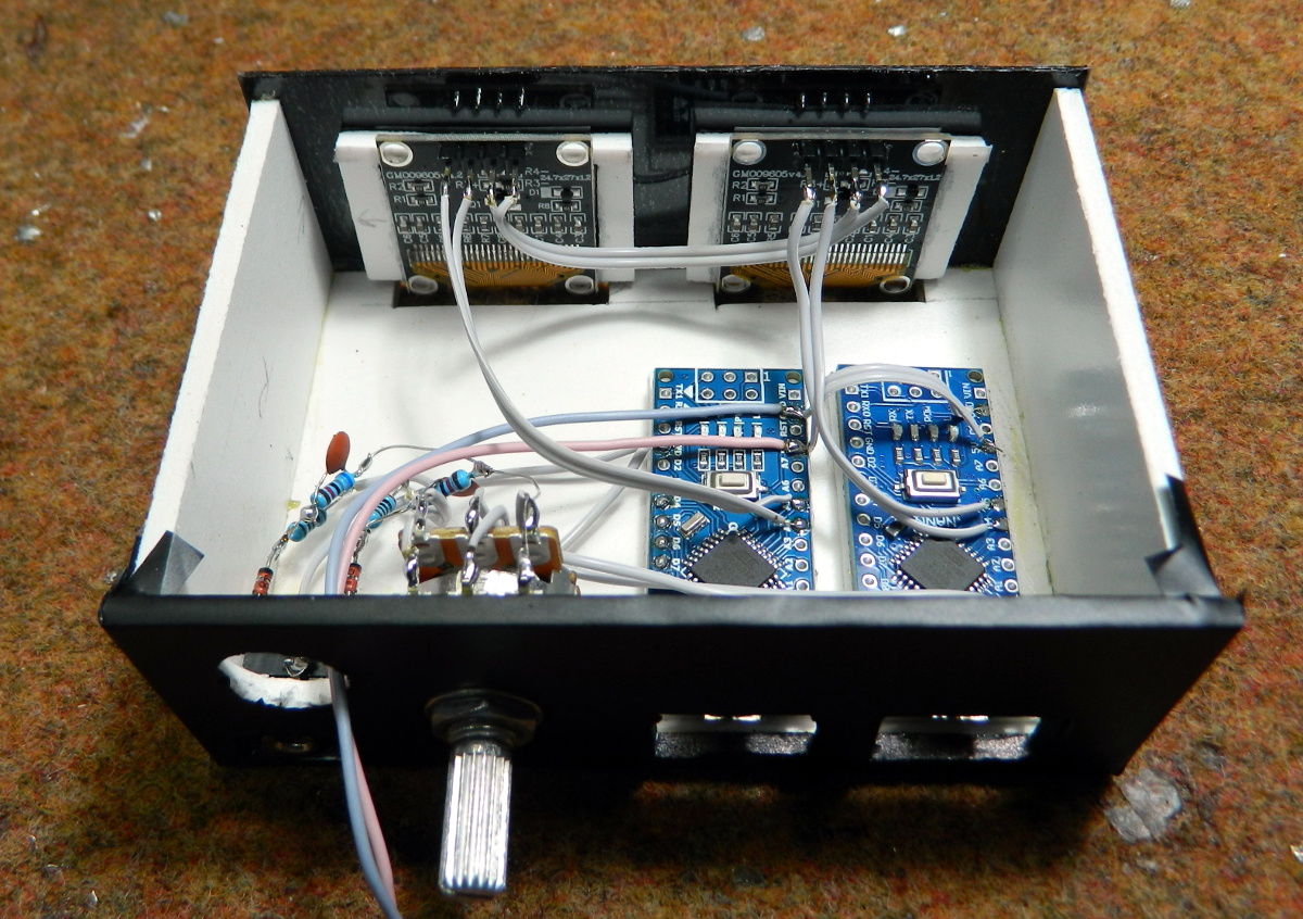 The project’s Hackaday.IO page explains that the idea is based on the work of [stevenart], with code adapted for the SSD1306 display and some tweaks made to the circuit. While [mircemk] says the code could be modified for stereo as long as the two displays don’t have conflicting I2C addresses, he decided to simply duplicate the whole setup for each channel to keep things simple. With as cheap as some of these parts are nowadays, it’s hard to blame him.
[mircemk] has provided source code for a couple different styles of VU indicators, the colors of which can easily be inverted depending on your tastes. He also clarifies that the jerky motion of the virtual “needle” seen in the video is due to the camera; in real-life it sweeps smoothly like the genuine article.
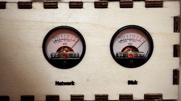
Much like the project that aimed to recreate authentic “steam gauges” with e-paper displays, this as an excellent technique to file away for use in the future. Compared to authentic analog gauges, these digital recreations are quicker and faster to implement, plus going this route prevents any antique hardware from going on the chopping block.
Continue reading “Analog Style VU Meter With Arduino And OLED Display”