There probably aren’t many people out there who aren’t aware of what thermite is and how it demonstrates the power of runaway exothermic reactions. Practical applications that don’t involve destroying something are maybe less known. This is where the use of thermite for creating welds is rather interesting, as shown in this video by [Finn] that is also embedded after the break.
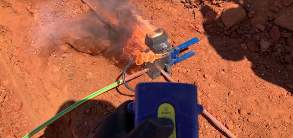
In the video, one can see how [Finn] uses thermite charges to weld massive copper conductors together in a matter of seconds inside a graphite mold. Straight joints, T-joints, and others are a matter of putting the conductors into the mold, pushing a button and watching the fireworks. After a bit of cleaning the slag off, a solid, durable weld is left behind.
The official name for this process is ‘exothermic welding‘, and it has been in use since the 19th century. Back then it was used primarily for rail welding. These days it sees a lot of use in high-voltage wiring and other applications, as in the linked video. The obvious advantage of exothermic welding is that the resulting joint is strong and durable, on account of the two surfaces having been permanently joined.
If you’ve seen both a fused filament fabrication (FFF) printer and a wire welder, you may have noticed that they work on a similar basic principle. Feedstock is supplied in filament form — aka wire — and melted to deposit on the work piece in order to build up either welds in the case of the welder, or 3D objects in the case of the printer. Of course, there are a number of difficulties that prevent you from simply substituting metal wire for your thermoplastic filament. But, it turns out these difficulties can be overcome with some serious effort. [Dominik Meffert] has done exactly this with his wire 3D printer project.
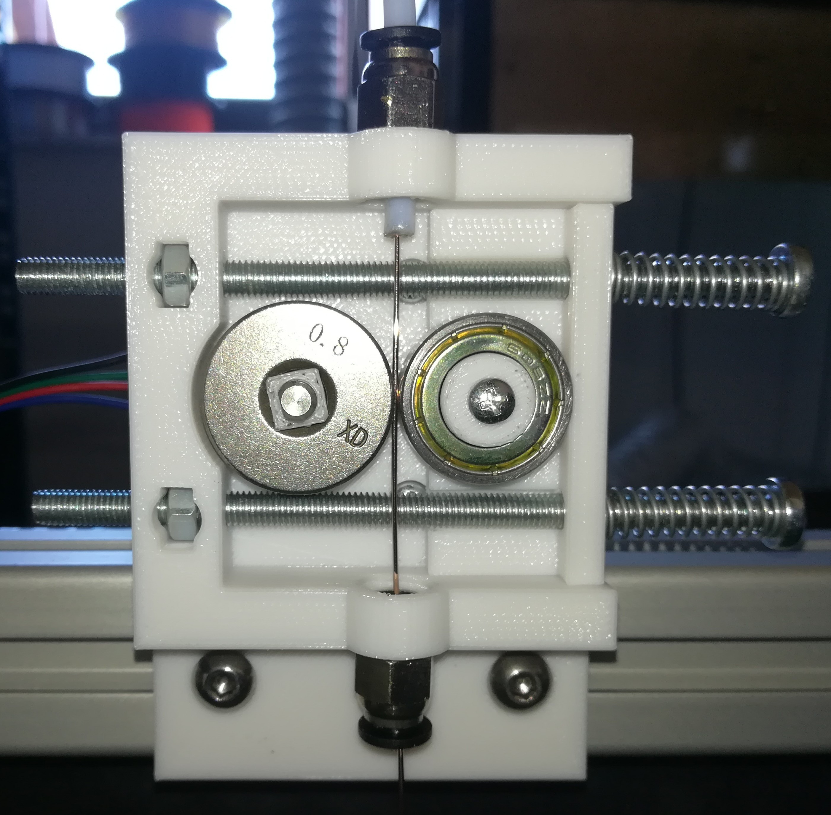
Extruder cold end using a standard feeder roller
For his filament, [Dominik] chose standard welding wire, and has also experimented with stainless steel and flux-cored wires. Initially, he used a normal toothed gear as the mechanism in the stepper-driven cold end of his Bowden-tube extrusion mechanism, but found a standard wire feeder wheel from a welder worked better. This pinch-drive feeds the wire through a Bowden tube to the hot end.
In thermoplastic 3D printers, the material is melted in a chamber inside the hotend, then extruded through a nozzle to be deposited. Instead of trying to duplicate this arrangement for the metal wire, [Dominik] used a modified microwave oven transformer (MOT) to generate the low-voltage/high-amperage required to heat the wire restively. The heating is controlled through a phase-fired rectifier power controller that modulates the power on the input of the transformer. Conveniently, this controller is connected to the cooling fan output of the 3D printer board, allowing any standard slicer software to generate g-code for the metal printer.
To allow the wire to heat and melt, there must be a complete circuit from the transformer secondary. A standard welding nozzle matching the wire diameter is used as the electrode on the hot end, while a metal build plate serves as the other electrode. As you can imagine, getting the build plate — and the first layer — right is quite tricky, even more so than with plastic printers. In this case, added complications involve the fact that the printed object must maintain good electrical continuity with the plate, must not end up solidly welded down, and the fact that the 1450 °C molten steel tends to warp the plate.
Considering all the issues that have to be solved to make this all work, we are very impressed with [Dominik’s] progress so far! Similar issues were solved years ago for the case of thermoplastic printers by a group of highly-motivated experimenters, and it’s great to see a similar thing starting to happen with metal printing, especially using simple, readily-available materials.
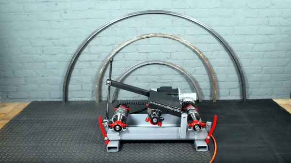
Every serious metal worker will end up getting themself a roller bender at some point, but if you’re as dedicated as [Meanwhile in the Garage], you might just start building the things yourself. His heavy-duty electric roller bender, demonstrated in the video after the break, is perfect for the thicker steel and bigger radii his smaller manual machine can’t handle.
The basic concept is the same in both machines, with two fixed rollers and a third adjustable opposing one between them. Most of the components are pieces of scrap metal, and each shaft runs on bearings mounted in homemade pillow blocks. The two fixed shafts are connected together by a chain drive, and a scrap industrial motor provides the rotating power through a worm gearbox. There are two adjustable bushings on each shaft to keep the work piece aligned. The lead screw from an old car jack is used to adjust the position of the moving roller.
We picked up a few interesting tips from the video, like how to properly align a cylindrical workpiece in a drill press for drilling radial holes. He also used toggle switches as limit switches in a pretty ingenious way, and F-clamps on the work piece to activate them when it reaches the end.
Building your own tools at home is a time-honoured hacking tradition, which we have never seen a shortage of here on Hackaday. Check out this DIY drill press and vertical CNC mill.
For those of us who were children in the late 80s and early 90s, we may have dreamed of one day owning a gigantic tractor trailer that could transform into a colossal fighting robot. Or of simply having a toy that could approximate this change from one form into another. As adults, though, we have come to realize that this is wishful thinking. That is, unless we decide to build this transforming bicycle.
What starts out as a slightly unusual-looking low rider-style bike effortlessly turns into a tall bike by means of a gas cylinder fixed to the bike’s rear triangle. The bike started out as a full suspension mountain bike, but the rear spring was removed to make room for this cylinder. The pivoting action of the rear triangle in a mountain bike is the key design element here: it allows the frame to change shape easily, in this situation when pushed by the cylinder. Adding some longer forks in the front and a coat of paint finishes the build.
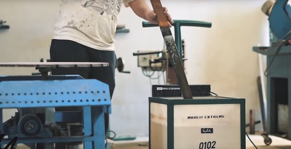
Anyone who’s done a bit of metalworking will know how quickly your stockpile will pick up a coating of rust with even just a bit of humidity. While welding requires only a bit of wire brushing at the joint areas, cleaning a large frame for paint is a completely different story. The projects [Make it Extreme] gets himself into tend to involve a lot of steel, so he built his own electrolysis tank for rust removal.
Electrolytic rust removal involves placing the piece of steel to be cleaned into an alkaline electrolyte solution (water and washing soda) with a sacrificial steel anode and connecting a low voltage DC supply over the two pieces. [Make it Extreme] started with an old plastic container, around which he built a very neat trolley frame. He obviously put some thought into how the tank will be cleaned, since it can be removed by unscrewing six bolts and removing the top part of the frame.
The high current, low voltage power supply that is required for the process was built using an old microwave transformer. The secondary coil is removed and replaced with coil of thick insulated wire, to convert it into a step down transformer. After the rewinding the transformer outputs about 13 VAC, which is then run through beefy bridge rectifier modules to get a DC current. A custom machined copper bolt terminal is mounted through the side of the tank to attach the sacrificial anode plate to the positive lead of the power supply, while the negative lead is clamped to the rusty steel to be cleaned.
Before you even ask, it’s an open source trackball and you’re gonna like it. Hackaday Editors Mike Szczys and Elliot Williams get down to brass tacks on this week’s hacks. From laying down fatter 3D printer extrusion and tricking your stick welder, to recursive Nintendos and cubic Castlevania, this week’s episode is packed with hacks you ought not miss.
Take a look at the links below if you want to follow along, and as always tell us what you think about this episode in the comments!
Take a look at the links below if you want to follow along, and as always, tell us what you think about this episode in the comments!
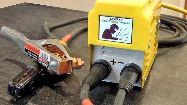
If you move in certain shady circles, you may have noticed the crop of improbably cheap “pocket welders” popping up on the market these days. They’re all variations on a theme, most with wildly optimistic specs minimal accessories of the lowest possible quality. But their tiny size and matching price make them irresistible to the would-be welder, as well as attractive to hardware hackers.
With a 220-V outlet in the garage waiting to be filled and well-knowing the risks, [Mr. RC-Cam] purchased one of these diminutive welding machines. Its shortcomings were immediately apparent, and a complete rework of the welder was undertaken. After addressing safety issues like the lack of a ground connection, [Mr. RC-Cam] added a color-matched 3D-printed hood to house a fancy new LCD touchscreen display. Backing that up is an ESP32 with Bluetooth, which supports remote control via a key fob. He also added a current sense board that uses the welder’s current shunt to measure welding current. Expediently calibrated using a waffle iron and a milli-ohmmeter, the sensor showed that the 200A max advertised for the welder was more like 100A. He tried adding some big electrolytics to fix the current issues, but no dice. With a decent stinger and ground clamp, the modified welder is good enough for his needs, and much was learned in the process. We call that a hacking win.