A recent writeup by Tom Nardi about using the 6502-based NES to track satellites brought back memories of my senior project at Georgia Tech back in the early 80s. At our club station W4AQL, I had become interested in Amateur Radio satellites. It was quite a thrill to hear your signal returning from space, adjusting for Doppler as it speeds overhead, keeping the antennas pointed, all while carrying on a brief conversation with other Earth stations or copying spacecraft telemetry, usually in Morse code.
yagi25 Articles
Lowering The Boom On Yagi Element Isolation
Antenna design can be confusing, to say the least. There’s so much black magic that goes into antennas that newbies often look at designs and are left wondering exactly how the thing could ever work. Slight changes in length or the angle between two elements result in a vastly different resonant frequency or a significant change in the antenna’s impedance. It can drive one to distraction.
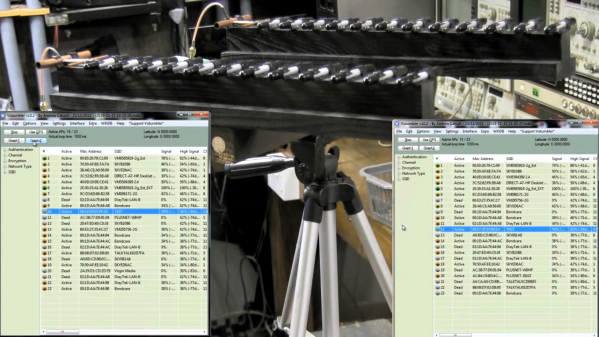
Particularly concerning are the frequent appearances of what seem to be dead shorts between the two conductors of a feedline, which [andrew mcneil] explored with a pair of WiFi Yagi antennas. These highly directional antennas have a driven element and a number of parasitic elements, specifically a reflector behind the driven element and one or more directors in front of it. Constructive and destructive interference based on the spacing of the elements and capacitive or inductive coupling based on their length determine the characteristics of the antenna. [Andrew]’s test antennas have their twelve directors either isolated from the boom or shorted together to the shield of the feedline. In side-by-side tests with a known signal source, both antennas performed exactly the same, meaning that if you choose to build a Yagi, you’ve got a lot of flexibility in what materials you choose and how you attach elements to the boom.
If you want to dive a little deeper into how the Yagi works, and to learn why it’s more properly known as the Yagi-Uda antenna, check out our story on their history and operational theory. And hats off to [andrew] for reminding us that antenna design is often an exercise in practicality; after all, an umbrella and some tin cans or even a rusty nail will do under the right circumstances.
Continue reading “Lowering The Boom On Yagi Element Isolation”
Beat Your Coat Hangers Into Antennas, Not Plowshares
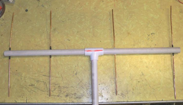
If you are looking for a fun project while you are cooped up and you have some spare coathangers, why not try this 4-element Yagi antenna (PDF)? [Pete N8PR] showed it off at his local ham radio club and it looked like something good for a lazy afternoon. If you aren’t a ham, you could adjust it all for a different VHF or UHF frequency.
For the boom, [Pete] mentions you can use wood, but it isn’t weather resistant. He chose half-inch PVC pipe. He also offers you a choice of material for the elements: #8 wire, welding rod, or — our favorite — coat hangers.
This is a big upgrade from a simple dipole or a vertical made from coax. The yagi should have about 8 dBi gain in the direction it is pointing. The center of the boom doesn’t have any elements, so that simplifies mounting. The insulating boom also makes mounting the driven element a breeze.
If you use the coat hangers, we’ve heard an easy way to get them very straight is to put one end on a vise and the other end in a drill chuck (see the video below). The method will weaken the wire, but the elements won’t have much stress. If it worries you, just go slow on the drill and you might consider annealing the wire with a torch afterward.
It would be easy to make this portable like some other designs we’ve seen. If you want the history and theory behind the venerable yagi antenna, you’ll want to revisit this post.
Continue reading “Beat Your Coat Hangers Into Antennas, Not Plowshares”
Keep An Eye On The Neighborhood With This Passive Radar
If your neighborhood is anything like ours, walking across the street is like taking your life in your own hands. Drivers are increasingly unconcerned by such trivialities as speed limits or staying under control, and anything goes when they need to connect Point A to Point B in the least amount of time possible. Monitoring traffic with this passive radar will not do a thing to slow drivers down, but it’s a pretty cool hack that will at least yield some insights into traffic patterns.
The principle behind active radar – the kind police use to catch speeders in every neighborhood but yours – is simple: send a microwave signal towards a moving object, measure the frequency shift in the reflected signal, and do a little math to calculate the relative velocity. A passive radar like the one described in the RTL-SDR.com article linked above is quite different. Rather than painting a target with an RF signal, it relies on signals from other transmitters, such as terrestrial TV or radio outlets in the area. Two different receivers are used, both with directional antennas. One points to the area to be monitored, while the other points directly to the transmitter. By comparing signals reflected off moving objects received by the former against the reference signal from the latter, information about the distance and velocity of objects in the target area can be obtained.
The RTL-SDR test used a pair of cheap Yagi antennas for a nearby DVB-T channel to feed their KerberosSDR four-channel coherent SDR, a device we last looked at when it was still in beta. Essentially four SDR dongles on a common board, it’s available now for $149. Using it to build a passive radar might not save the neighborhood, but it could be a lot of fun to try.
This Mostly 3D-Printed Discone Antenna Is Ready For Broadband Duty
For hams and other radio enthusiasts, the best part of the hobby is often designing antennas. Part black magic, part hard science, and part engineering, antenna design is an art. And while the expression of that art often ends up boiling down to pieces of wire cut to the correct length, some antennas have a little more going on in the aesthetics department.
Take the discone antenna, for example. Originally designed as a broadband antenna to sprout from aircraft fuselages, the discone has found a niche with public service radio listeners. But with a disk stuck to the top of a cone, the antennas have been a little hard to homebrew, at least until [ByTechLab] released this mostly 3D-printed discone. A quick look at the finished product, resembling a sweater drying rack more than a disc on top of a cone, reveals that the two shapes can be approximated by individual elements instead of solid surfaces. This is the way most practical discones are built, and [ByTechLab]’s Thingiverse page has the files needed to print the parts needed to properly orient the elements, which are just 6-mm aluminum rods. The printed hub pieces sandwich a copper plate to tie the elements together electrically while providing a feedpoint for the antenna as well as a sturdy place to mount it outdoors. This differs quite a bit from the last 3D-printed discone we featured, which used the solid geometry and was geared more for indoor use.
Interested in other antenna designs? Who can blame you? Check out the theory behind the Yagi-Uda beam antenna, or how to turn junk into a WiFi dish antenna.
[via RTL-SDR.com]
On Point: The Yagi Antenna
If you happened to look up during a drive down a suburban street in the US anytime during the 60s or 70s, you’ll no doubt have noticed a forest of TV antennas. When over-the-air TV was the only option, people went to great lengths to haul in signals, with antennas of sometimes massive proportions flying over rooftops.
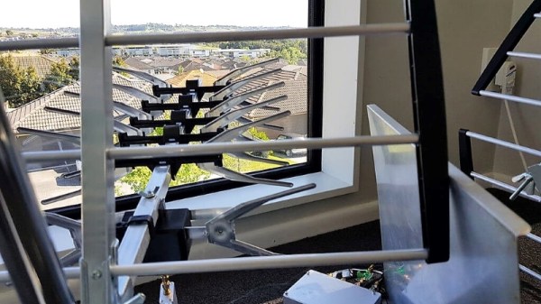
Outdoor antennas all but disappeared over the last third of the 20th century as cable providers became dominant, cast to the curb as unsightly relics of a sad and bygone era of limited choices and poor reception. But now cheapskates cable-cutters like yours truly are starting to regrow that once-thick forest, this time lofting antennas to receive digital programming over the air. Many of the new antennas make outrageous claims about performance or tout that they’re designed specifically for HDTV. It’s all marketing nonsense, of course, because then as now, almost every TV antenna is just some form of the classic Yagi design. The physics of this antenna are fascinating, as is the story of how the antenna was invented.
Simple Scanner Finds The Best WiFi Signal
Want to know which way to point your WiFi antenna to get the best signal? It’s a guessing game for most of us, but a quick build of a scanning WiFi antenna using mostly off-the-shelf components could point you in the right direction.
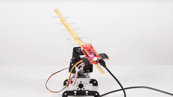
With saturation WiFi coverage in most places these days, optimizing your signal might seem like a pointless exercise. And indeed it seems [shawnhymel] built this more for fun than for practical reasons. Still, we can see applications where a scanning Yagi-Uda antenna would come in handy. The build started with a “WiFi divining rod” [shawnhymel] created from a simple homebrew Yagi-Uda and an ESP8266 to display the received signal strength indication (RSSI) from a specific access point. Tired of manually moving the popsicle stick and paperclip antenna, he built a two-axis scanner to swing the antenna through a complete hemisphere.
The RSSI for each point is recorded, and when the scan is complete, the antenna swings back to the strongest point. Given the antenna’s less-than-perfect directionality — [shawnhymel] traded narrow beam width for gain — we imagine the “strongest point” is somewhat subjective, but with a better antenna this could be a handy tool for site surveys, automated radio direction finding, or just mapping the RF environment of your neighborhood.
Yagi-Uda antennas and WiFi are no strangers to each other, whether it be a WiFi sniper rifle or another recycling bin Yagi. Of course this scanner isn’t limited to WiFi. Maybe scanning a lightweight Yagi for the 2-meter band would be a great way to lock onto the local Ham repeater.
Continue reading “Simple Scanner Finds The Best WiFi Signal”

