Fixing A C64 With A Cheap $20 Oscilloscope

Modern computers are so fast and complex that we would seldom try and fix them on a component level with simple DIY tools. Working on an early 1980s computer is much easier by comparison, with the fastest signals often in the single-MHz range. [Sayaka] demonstrates this by using a cheap $20 oscilloscope to troubleshoot and repair a Commodore 64.

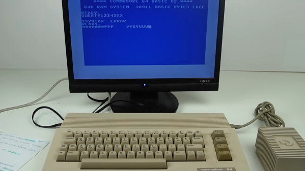
After powering it up for the first time, the C64 displays a BASIC prompt, but none of the keys seem to work. [Sayaka] did what good hackers do, and immediately disassembled it to try and figure out the problem, suspecting the CIA chip as a likely culprit.

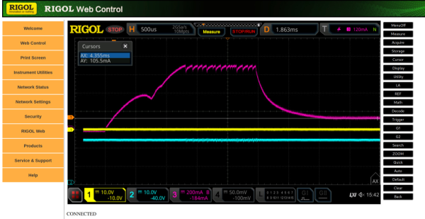
[Sayaka] elected to purchase a cheap DS0138 oscilloscope kit to help troubleshoot the C64. It’s not the most capable thing, with a bandwidth of just 200 KHz, but it’s enough to do some work on an old retro machine. After probing around to check a number of signals, she noted that the CIA’s pins seemed to be very oxidized and suffering poor conductivity. All it took from there was a resolder job, and the computer was repaired.

We’ve seen other cheap scopes with altogether more impressive specs, too. Video after the break. Continue reading “Fixing A C64 With A Cheap $20 Oscilloscope”

The Reverse Oscilloscope

Usually, an oscilloscope lets you visualize what a signal looks like. [Mitxela]’s reverse oscilloscope lets you set what you want an audio waveform to look like, and it will produce it. You can see the box in the video below.

According to [Mitxela] part of the difficulty in building something like this is making the controls manageable for mere mortals. We really like the slider approach, which seems pretty obvious, but some other controls are a bit more subtle. For example, the interpolation control can create a squarish wave or a smooth waveform, or anything in between.

This is sort of an artistic take on an arbitrary waveform generator but with a discrete-panel user interface. The device contains a Teensy, a Raspberry PI Pico, a 16-bit ADC, and an external DAC. The Pico is little more than an I/O controller, reading the user interface and transmitting it on a serial port.

The outside construction looks excellent (we assume the tape is temporary). The inside is a bit messier, but still nicely done. There are many photos of the construction and details of problems along the way with 12-bit ADCs and power supply experiments.

Of course, if you don’t need the user interface, you can go crazy with waveform generation. We did our own similar project, but you could draw your waveforms on the PC instead of sliders.

Continue reading “The Reverse Oscilloscope”

Spinning CRT Makes A 360 Degree Audio Oscilloscope

A question for you: if the cathode ray tube had never been invented, what would an oscilloscope look like? We’re not sure ourselves, but it seems like something similar to this mechanical tachyscope display might worked, at least up to a point.

What’s ironic about this scenario is that the tachyscope [Daniel Ross] built actually uses a CRT from a defunct camcorder viewfinder as the light-up bit of what amounts to a large POV display. The CRT’s horizontal coil is disconnected while the vertical coil is attached to the output of a TEA205B audio amplifier. The CRT, its drive electronics, and the amp are mounted to a motorized plastic platter along with a wireless baby monitor, to send audio to the CRT without the need for slip rings — although a Bluetooth module appears to be used for that job in the video below.

Speaking of slip rings, you’d expect one to make an appearance here to transfer power to the platter. [Daniel] used a slip ring for his previous steampunk tachyscope, but this time out he chose a hand-wound air core transformer, with a stationary primary coil and secondary coil mounted on the platter. With a MOSFET exciter on the primary and a bridge rectifier on the secondary, he’s able to get the 12 volts needed to power everything on the platform.

Like most POV displays, this one probably looks better in person than it does in video. But it’s still pretty cool, with the audio waveforms sort of floating in midair as the CRT whizzes around. [Daniel] obviously put a lot of work into this, not least with the balancing necessary to get this running smoothly, so hats off for the effort.

Continue reading “Spinning CRT Makes A 360 Degree Audio Oscilloscope”

STM32 Oscilloscope Uses All The Features

[jgpeiro] is no slouch when it comes to building small, affordable oscilloscopes out of common microcontrollers. His most recent, based on an RP2040 with two channels that ran at 100 MSps, put it on the order of plenty of commercially-available oscilloscopes at this sample rate but at a fraction of the price. He wanted to improve on the design though, making a smaller unit with a greatly reduced bill-of-materials and with a more streamlined design, so he came up with this STM32-based oscilloscope.

The goal of this project was to base as many of the functions around the built-in capabilities of the STM32 as possible, so in addition to the four input channels and two output channels running at 1 MHz, the microcontroller also drives a TFT display which has been limited to 20 frames per second to save processor power for other tasks. The microcontroller also has a number of built-in operational amplifiers which are used as programmable gain amplifiers, further reducing the amount of support circuitry needed on the PCB while at the same time greatly improving the scope’s capabilities.

In fact, the only parts of consequence outside of the STM32, the power supply, and the screen are the inclusion of two operational amplifiers included to protect the input channels from overvoltage events. It’s an impressive build in a small form factor, and we’d say the design goal of keeping the parts count low has been met as well. If you do need something a little faster though, his RP2040-based oscilloscope is definitely worth checking out.

Continue reading “STM32 Oscilloscope Uses All The Features”

The Right Equipment Makes A Difference For Digital Oscilloscope Music

We all love our cheap digital oscilloscopes, and with good reason. But if there’s one place where analog scopes still shine, it’s anywhere you need X-Y mode. Digitally sampling the inputs and mapping them on the screen as discrete points just isn’t the same as steering an electron beam around a CRT, making X-Y mode work on digital scopes — at least the affordable ones — somewhat lacking.

Thankfully, nobody told [Mark Hughes] that his digital scope would make a lousy X-Y display, so he just plunged ahead and figured out how to make it work anyway. The results are actually pretty good, but it took some doing. His setup begins with OsciStudio, an application built to take 3D shapes and animations and turn them into oscilloscope music. The output from that is piped to a USB sound card; [Mark] used a PreSonus Studio 26c, an adapter with DC-coupled inputs, which he found to be critical to getting good images. Also important was a USB isolator and good-quality cables, which greatly reduced jitter and made the image much more stable.

Displaying the image was as easy as connecting the left and right outputs from the sound card to the two scope inputs — [Mark] used a Keysight EDUX1052G — and setting it to X-Y mode. It took a fair amount of fiddling to get as far as he did, but we think the results speak for themselves. As for the sounds made by these images, he says it’s a bit like a hung sound card when a computer blue-screens. So, yeah — not exactly musical, but still an interesting way to have some fun with your digital scope.

Remote Code Execution On An Oscilloscope

There are a huge number of products available in the modern world that come with network connectivity now, when perhaps they might be better off with out it. Kitchen appliances like refrigerators are the classic example, but things like lightbulbs, toys, thermostats, and door locks can all be found with some sort of Internet connectivity. Perhaps for the worse, too, if the security of these devices isn’t taken seriously, as they can all be vectors for attacks. Even things like this Rigol oscilloscope and its companion web app can be targets.

The vulnerability for this oscilloscope starts with an analysis of the firmware, which includes the web control application. To prevent potentially bricking a real oscilloscope, this firmware was emulated using QEMU. The vulnerability exists in the part of the code which involves changing the password, where an attacker can bypass authentication by injecting commands into the password fields. In the end, the only thing that needs to be done to gain arbitrary code execution on the oscilloscope is to issue a curl command directed at the oscilloscope.

In the end, [Maunel] suggests not connecting this oscilloscope to the Internet at all. He has informed the producer about it but as of this writing there has not been a resolution. It does, however, demonstrate the vulnerabilities that can be present in network-connected devices where the developers of the software haven’t gone to the lengths required to properly secure them for use with the modern Internet. Even things not connected to a traditional Internet connection can be targets for attacks.

Retro Gadgets: The 1983 Pocket Oscilloscope

In the 1980s, an oscilloscope was typically a bulky affair with a large CRT, and a heavy power supply. So it probably grabbed a lot of attention in 1983 when Calvert Instruments Incorporated ran an ad in magazines like Radio Electronics. The ad touted a 5 MHz scope that was pocket-sized and weighed 4 ounces. The ad proudly proclaimed: CRT oscilloscopes just became obsolete!

Indeed they would, but if you are wondering who Calvert Instruments was, so are we. We have never heard of them before or since, and we don’t know for certain if any of these devices were ever actually produced. What did it use instead of a CRT? The CI Model 210 Pocket-O-Scope was not only solid state but used an LED screen 1.5 inches square. That’s small, but it packed in 210 LEDs for “high resolution.” We assume that was also the genesis of the model number. Judging from the product picture, there were 14 LEDs in the X direction and 15 in the Y direction. High resolution, for sure!

There were some early LCD scopes (like the Iskrascope and one from Scopex) around the same time, but it would be the 1990s before we would see LCD oscilloscopes and even longer before CRTs were totally squeezed out.

Continue reading “Retro Gadgets: The 1983 Pocket Oscilloscope”