A two picture montage of a boy wearing a sonic the hedgehog costume with LEDs in them. The left picture is at night with the boy wearing sunglasses and a face mask with the sonic costume head piece lit up. The right picture is during the day with the boy wearing a face mask, holding a plastic pu mpkin bucket for candy and wearing a lit up sonic the hedgehog costume in the front yard of a house.

LEDs Put New Spin On A Sonic The Hedgehog Costume

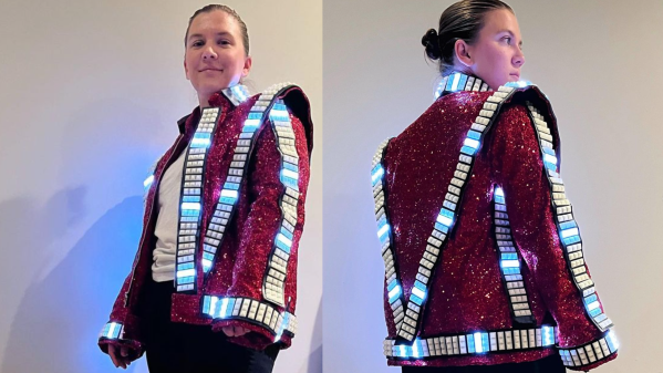
[Wentworthm] couldn’t say no to his son’s plea for a Sonic the Hedgehog costume for Halloween but also couldn’t resist sprucing it up with LEDs either. The end result is a surprisingly cool light up Sonic the Hedgehog costume.

a picture of a breadboard with an Arduino Nano on it, with wires going out to 3d printed tear dropped shapes that have LED strips in them, with some LED strips on.

After some experimentation, [Wentworthm] ordered two costumes and ended up mixing and matching the head piece of one with the body suit of the other. For the head, [Wentworthm] created six 3D printed “quills” that had slots for the WS2812B LED strips to slide into and diffuse out the sides, with each quill sliding into the folds of the Sonic head “spikes”. Sewn strips of cloth were used to house the LED strips that were placed down the sides of the costume. An additional 3D printed switch housing was created to allow for a more robust interface to the two push buttons to activate the LEDs. An Arduino Nano, soldered to a protoboard, was used to drive the LED strips with a USB battery pack powering the whole project.

[Wentworthm] goes into more detail about the trials and errors, so the post is definitely worth checking out for more detail on the build. Halloween is always a great source of cool costumes and we’ve featured some great ones before, like a light up crosswalk costume to making a giant Gameboy colour costume.

Video after the break!

Continue reading “LEDs Put New Spin On A Sonic The Hedgehog Costume”

A Gaggia classic espresso machine with an LCD screen attached to the top, sitting on a table with vase of yellow lily flowers to its left and sunlight coming in from a window from the right.

Homebrew Espresso Maker Modding With Gaggiuino

For those that don’t know, Gaggia is a company that produces a line of affordable “entry-level” espresso coffee makers that offer good quality consumer espresso machines at reasonable prices. The entry level machines don’t offer fine grained control over temperature, pressure and steam which is where the Gaggiuino project comes in.

A schematic of the Gagguino project

The Gaggiuino project is an “after market” modification of many espresso makers, such as the Gaggia classic and Gaggia classic pro. The main additions are a MAX6675 thermocouple module paired with a K-Type thermocouple sensor for closed loop control over the temperature. Options for adding an AC dimmer module that attaches to the pump motor and a 0 Mpa to 1.2 Mpa ranged XDB401 pressure sensor, installed in line between the pump and the boiler, provide further closed loop control over the pressure and flow profiling.

Load cells can be attached to the drip tray to allow for feedback about the pour weight with a Nextion 2.4″ LCD touchscreen provides the user interface for profile selection and other interactivity. The project offers a “base” modification using an Arduino Nano as the microcontroller, in line with its namesake, but has an option for an STM32 Blackpill module that can provide more functionality beyond the scope of the Nano.

The Gaggiuino project is open source with code and extensive documentation available on GitHub. There is also a Discord community for those wanting help with their build or that have the inclination to share their passion for DIY espresso modding with the Gaggiuino. Espresso machine hacks are a favorite of ours and we’ve featured many projects on espresso machine builds and mods ranging from PID control of classic espresso makers to beautifully minimal closed loop homebrew espresso machines.

Continue reading “Homebrew Espresso Maker Modding With Gaggiuino”

"The Great Resistor" color code illumination project

The Great Resistor Embiggens The Smallest Value

With surface-mount components quickly becoming the norm, even for homebrew hardware, the resistor color-code can sometimes feel a bit old-hat. However, anybody who has ever tried to identify a random through-hole resistor from a pile of assorted values will know that it’s still a handy skill to have up your sleeve. With this in mind, [j] decided to super-size the color-code with “The Great Resistor”.

Resistor color code from Wikipedia with white background
How the resistor color-code bands work

At the heart of the project is an Arduino Nano clone and a potential divider that measures the resistance of the test resistor against a known fixed value. Using the 16-bit ADC, the range of measurable values is theoretically 0 Ω to 15 MΩ, but there are some remaining issues with electrical noise that currently limit the practical range to between 100 Ω and 2 MΩ.

[j] is measuring the supply voltage to help counteract the noise, but intends to move to an oversampling/averaging method to improve the results in the next iteration.

The measured value is shown on the OLED display at the front, and in resistor color-code on an enormous symbolic resistor lit by WS2812 RGB LEDs behind.

Inside view of the great resistor showing WS2812 LEDs and baffle plates
Inside The Great Resistor, the LEDs and baffle plates make the magic work

Precision aside, the project looks very impressive and we like the way the giant resistor has been constructed. It would look great at a science show or a demonstration. We’re sure that the noise issues can be ironed out, and we’d encourage any readers with experience in this area to offer [j] some tips in the comments below. There’s a video after the break of The Great Resistor being put through its paces!

If you want to know more about the history of the resistor color code bands, then we have you covered.  Alternatively, how about reading the color code directly with computer vision?

Continue reading “The Great Resistor Embiggens The Smallest Value”

Two shots of a Thriller jacket with LED strips being worn by Louise Katzovitz, one from the front and the other from the back.

Thrills With An LED “Thriller” Jacket

[Louise Katzovitz] has created a light-up jacket in the style of the jacket worn by Michael Jackson in the 1983 music video for “Thriller”. [Louise Katzovitz]’s Thriller jacket is the perfect example of combining sewing hacks and electronic hacks to make an awesome, wearable jacket.

A bomber jacket was used as the base form to layer on the sequins and LED strips. Instead of bands of metal studs, [Louise] used WS2812B 60 pixels/m LED strips. 3D-printed transparent PLA “gems” were placed on top of the LEDs to mimic the form of the metal studs in the original jacket and provide diffusion for the underlying LEDs.

Inside of the LED thriller jacket, with battery pack, arduino nano and wiring exposed

Each LED strip was laid out on a piece of vinyl strip. Then, a top layer of vinyl was cut to allow each of the LEDs to poke through, with the 3D printed gems super-glued on top. The assembled LED bands are attached to the jacket by Velcro with the wiring fed behind the lining material, which can be removed easily via small hooks. The whole thing is driven by an Arduino Nano and a 5 V power bank.

With the details and process worked out, [Louise] even made a tiny version of the jacket for her dog. We’ve featured LED wearables and fashion before and [Louise]’s jacket is a great addition. These projects are perfect for anyone who wants to wow their friends this upcoming Halloween season. Video after the break!

Continue reading “Thrills With An LED “Thriller” Jacket”

A machine that holds a combination padlock and turns its dial, with two padlocks next to it

Robot Opens Master Combination Locks In Less Than A Minute

A common trope in bank heist B-movies is someone effortlessly bypassing a safe’s combination lock. Typically, the hero or villain will turn the dial while listening to the internal machinery, then deduce the combination based on sounds made by the lock. In real life, high-quality combination locks are not vulnerable to such simple attacks, but cheap ones can often be bypassed with a minimum of effort. Some are so simple that this process can even be automated, as [Mew463] has shown by building a machine that can open a Master combination lock in less than a minute.

A machine that holds a combination padlock and turns its dialThe operating principle is based on research by Samy Kamkar from a couple of years ago. For certain types of Master locks, the combination can be found by applying a small amount of pressure on the shackle and searching for locations on the dial where its movement becomes heavier. A simple algorithm can then be used to completely determine the first and third numbers, and find a list of just eight candidates for the second number.

[Mew463]’s machine automates this process by turning the dial with a stepper motor and pulling on the shackle using a servo and a rack-and-pinion system. A magnetic encoder is mounted on the stepper motor to determine when the motor stalls, while the servo has its internal position encoder brought out as a means of detecting how far the shackle has moved. All of this is controlled by an Arduino Nano mounted on a custom PCB together with a TMC2208 stepper driver.

The machine does its job smoothly and quickly, as you can see in the (silent) video embedded below. All design files are available on the project’s GitHub page, so if you’ve got a drawer full of these locks without combinations, here’s your chance to make them sort-of-useful again. After all, these locks’ vulnerabilities have a long history, and we’ve even seen automated crackers before.

Continue reading “Robot Opens Master Combination Locks In Less Than A Minute”

Hacking A Jack-in-the-Box To Be Extra Surprising

A Jack-In-The-Box is scary enough the first time. However, if you’ve seen the clown pop out before, it fails to have the same impact. [Franklinstein] decided that swapping out the clown for an alternative payload would deliver the fright he was after.

Inside the toy, an Arduino Nano runs the show. It’s paired with an airhorn, installed in a special frame along with an RC servo. When the time is right, the RC servo presses up against the airhorn, firing off an almighty noise. There’s also a confetti blaster, built with a small chamber full of compressed air. When a solenoid is released, the compressed air rushes out through a funnel full of confetti, spraying it into the room.

When the crank on the toy is turned, the typical song plays. When the lid of the box opens, it releases a switch, and the Arduino fires off the confetti and airhorn. It’s shocking enough for [Franklinstein] himself, and even more surprising for those expecting the toy’s typical bouncing clown instead.

We’d love to see an even more obnoxious version that doesn’t turn the airhorn off for at least a full minute. We’ve seen them employed in some great Halloween hacks before, too. Video after the break.

Continue reading “Hacking A Jack-in-the-Box To Be Extra Surprising”

Fireball-Flinging Figurine Feeds Fiction

If you’re writing a screenplay or novel, there will likely be points along the way at which you can’t get enough encouragement from friends and family. While kind words are kind, acts such as [scubabear]’s can provide a push like no other. By commissioning another 3D designer friend to model a character from the first friend’s screenplay so he could print and animate it, [scubabear] fed two birds with one scone, you might say.

Designer friend [Sean] modeled the mighty Braomar in Maya and Z-brush, and [scubabear] did test prints on a Formlabs Form2 as they went along to keep an eye on things. Eventually, they had a discussion about making space for wires and such, so [Sean] took to Blender to make Braomar hollow enough for wires, but not so empty that he would collapse under the stress of being (we presume) the main character.

Braomar stands upon a sigil that changes color thanks to an RGB LED ring in the base that’s driven by an Arduino Nano. A single pixel in the fireball is wired through Braomar’s body and flickers with the help of an addressable LED sequencer board.

Our favorite part of this build has to be the power scheme. Not content to have a wire running out from the base or even a remote control for power-draining concerns, [scubabear] used disc magnets in the base to switch on the 9 V battery when Screenplay Friend rotates it.

Of course, if you need inspiration to even thing about beginning to write a screenplay or novel, maybe you should lead with the maquette-building and then construct a story around your creation.


This project was an entry into the 2022 Sci-Fi Contest. Check out all of the winning entries here.