Signal Generator Uses FPGA

Although there are a few exceptions, FPGAs are predominantly digital devices. However, many FPGA applications process analog data, so you often see an FPGA surrounded by analog and digital converters. This is so common that Opal Kelly — a producer of FPGA tools — launched the SYZYGY open standard for interconnecting devices like that. [Armeen] — a summer intern at Opal Kelly — did a very interesting open source FPGA-based signal generator using a Xilinx FPGA, and a SYZYGY-compliant digital to analog converter.

As you might expect, [Armeen] used a lot of Opal Kelly hardware and software in the project. But the Verilog code (available on GitHub) shows a lot of interesting things including some very practical example code for using Xilinx CORDIC IP,  which is a great way to do high-order math using digital logic.

Continue reading “Signal Generator Uses FPGA”

Review: FG-100 DDS Function Generator

I don’t have a signal generator, or more specifically I don’t have a low frequency signal generator or a function generator. Recently this fact collided with my innocent pleasure in buying cheap stuff of sometimes questionable quality. A quick search of your favourite e-commerce site and vendor of voice-controlled internet appliances turned up an FG-100 low frequency 1Hz to 500kHz DDS function generator for only £15 ($21), what was not to like? I was sold, so placed my order and eagerly awaited the instrument’s arrival.

The missing function generator is a gap in the array of electronic test instruments on my bench, and it’s one that maybe isn’t as common a device as it once might have been. My RF needs are served by a venerable Advance signal generator from the 1960s, a lucky find years ago in the back room of Stewart of Reading, but at the bottom end of the spectrum my capabilities are meagre. So why do I need another bench tool?

It’s worth explaining what these devices are, and what their capabilities should be. In simple terms they create a variety of waveforms at a frequency and amplitude defined by their user. In general something described as a signal generator will only produce one waveform such as a sine or a square wave, while a function generator will produce a variety such as sine, square, and sawtooth waves. More accomplished function generators will also allow the production of arbitrary waveforms defined by the user. It is important that these instruments have some level of calibration both in terms of their frequency and the amplitude of their output. It is normal for the output to range from a small fraction of a volt to several volts. How would the FG-100 meet these requirements? Onward to my review of this curiously inexpensive offering.

Continue reading “Review: FG-100 DDS Function Generator”

Tiny Function Generator On The ATtiny85, Complete With OLED

It’s easy to have a soft spot for “mini” yet perfectly functional versions of electronic workbench tools, like [David Johnson-Davies]’s Tiny Function Generator which uses an ATtiny85 to generate different waveforms at up to 5 kHz. It’s complete with a small OLED display to show the waveform and frequency selected. One of the reasons projects like this are great is not only because they tend to show off some software, but because they are great examples of the kind of fantastic possibilities that are open to anyone who wants to develop an idea. For example, it wasn’t all that long ago that OLEDs were exotic beasts. Today, they’re available off the shelf with simple interfaces and sample code.

The Tiny Function Generator uses a method called DDS (Direct Digital Synthesis) on an ATtiny85 microcontroller, which [David] wrote up in an earlier post of his about waveform generation on an ATtiny85. With a few extra components like a rotary encoder and OLED display, the Tiny Function Generator fits on a small breadboard. He goes into detail regarding the waveform generation as well as making big text on the small OLED and reading the rotary encoder reliably. His schematic and source code are both available from his site.

Small but functional microcontroller-based electronic equipment are nifty projects, and other examples include the xprotolab and the AVR-based Transistor Tester (which as a project has evolved into a general purpose part identifier.)

Guitar Game Plays With Enhanced Realism

There’s a lot more to learning how to play the guitar than just playing the right notes at the right time and in the right order. To produce any sound at all requires learning how to do completely different things with your hands simultaneously, unless maybe you’re a direct descendant of Eddie Van Halen and thus born to do hammer ons. There’s a bunch of other stuff that comes with the territory, like stringing the thing, tuning it, and storing it properly, all of which can be frustrating and discouraging to new players. Add in the calluses, and it’s no wonder people like Guitar Hero so much.

[Jake] and [Jonah] have found a way to bridge the gap between pushing candy colored buttons and developing fireproof calluses and enough grip strength to crush a tin can. For their final project in [Bruce Land]’s embedded microcontroller design class, they made a guitar video game and a controller that’s much closer to the experience of actually playing a guitar. Whether you’re learning to play for real or just want to have fun, the game is a good introduction to the coordination required to make more than just noise.

Continue reading “Guitar Game Plays With Enhanced Realism”

Arduino RF Network Analyzer

What do you get when you combine a direct digital synthesis (DDS) chip, a power detector, and an Arduino? [Brett Killion] did make that combination and wound up with a practical network analyzer.

The project uses an Analog Devices AD9851 DDS chip clocked at 180 MHz which will output a sine wave at any frequency from 0 Hz and 72 MHz. A Butterworth low pass filter processes the DDS signal and then feeds a two-transistor amplifier. The circuit will output about 0dBm into 50 ohms. The power detector is an Analog Devices AD8307 along with a 50-ohm input load. There is no filtering on the power detector so it can measure from very low frequencies to 500MHz.

Continue reading “Arduino RF Network Analyzer”

A Slew Of Open-Source Synthesizers

Hackaday reader [Jan Ostman] has been making microcontroller-based DIY synthesizers for quite a while now. Recently, he’s opened up the source for a lot of them so that you can play along at home. All of these virtual-analog synths and soundmakers can be realized on an Arduino or AVR ATmega328 if you happen to have one lying around.

Extra parts like a keyboard, some pushbuttons, or some potentiometer knobs to twiddle won’t hurt if you’d like to make something more permanent or more obviously playable, like [Jan] does. On the other hand, if you’d just like to get your feet wet, I’ve tweaked his code to be more immediately plug-and-play. The code is straightforward enough that it’s a good learning platform. So let’s take a quick tour through three drum machines and a string synth, each of which you can build on a breadboard in just a few minutes.

To install on an Arduino UNO, fetch the zip file from this GitHub repository, and move each subfolder to your Arduino sketch directory. You’re ready to play along.

Continue reading “A Slew Of Open-Source Synthesizers”

$40 Antenna Analyzer With Arduino And AD9850

If you are a hacker, you might consider ham radio operators as innovative. Most people, however, just see them as cheap. So it is no surprise that hams like [jmharvey] will build an antenna analyzer from a DDS module and an Arduino instead of dropping a few hundred dollars on a commercial unit. As he points out, you probably only need an analyzer for a day or two while you set up an antenna. Unless you are a big time antenna builder, the unit will then sit idle on the shelf (or will wind up on loan to hams even cheaper than you are).

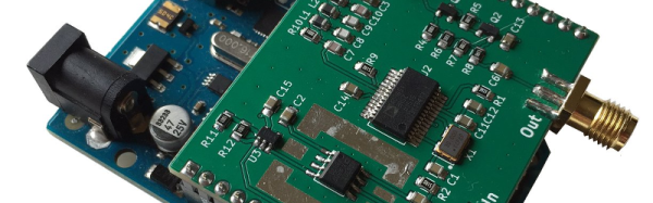
The design is rooted in another proven design, but changed to take advantage of parts he happened to have on hand. Although the build is on a universal circuit board, [jmharvey] used Eagle to lay out the circuit as though it were a PCB. Since placement can be important with an RF circuit, this isn’t a bad idea. It’s always easier to move stuff around on the screen than on the perf board.

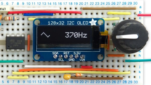
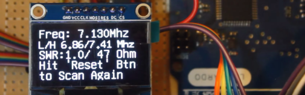
Since this is a no frills, unit, you are expected to grab the output from the Arduino and manually put it in a spreadsheet to plot the results. There is another version of the Arduino code that drives an OLED screen, although you still need a PC to kick the process off. One interesting feature of the Arduino code is how it deals with the nonlinear nature of the diodes used in the circuit. After plotting the values with known loads, [jmharvey] broke the diode operation into three regions and used different equations for each region. Even so, he warns that readings higher than 1:1 VSWR are only accurate to 10% or 20% – still good enough for ham shack use.

If you want an antenna analyzer for $40 (or less, if you have a good stock of parts) this looks like a worthwhile project. If, however, you want to repurpose it to Rickroll your neighbor’s AM radio, you might want to go with the commercial unit.

Click past the break to see the analyzer in action.

Continue reading “$40 Antenna Analyzer With Arduino And AD9850”