Siphoning Energy From Power Lines

The discovery and implementation of alternating current revolutionized the entire world little more than a century ago. Without it, we’d all have inefficient, small neighborhood power plants sending direct current in short, local circuits. Alternating current switches the direction of current many times a second, causing all kinds of magnetic field interactions that result in being able to send electricity extremely long distances without the resistive losses of a DC circuit. The major downside, though, is that AC circuits tend to have charging losses due to this back-and-forth motion, but this lost energy can actually be harvested with something like this custom-built transformer.

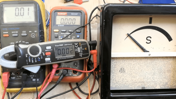
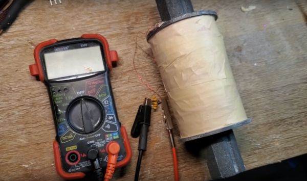
[Hyperspace Pilot] hand-wound this ferromagnetic-core transformer using almost two kilometers of 28-gauge magnet wire. The more loops of wire, the more the transformer will be able to couple with magnetic fields generated by the current flowing in other circuits. The other thing that it needs to do is resonate at a specific frequency, which is accomplished by using a small capacitor to tune the circuit to the mains frequency. With the tuning done, holding the circuit near his breaker panel with the dryer and air conditioning running generates around five volts. There’s not much that can be done with this other than hook up a small LED, since the current generated is also fairly low, but it’s an impressive proof of concept.

After some more testing, [Hyperspace Pilot] found that the total power draw of his transformer is only on the order of about 50 microwatts in an ideal setting where the neutral or ground wire wasn’t nearby, so it’s not the most economical way to steal electricity. On the other hand, it could still be useful for detecting current flow in a circuit without having to directly interact with it. And, it turns out that there are better ways of saving on your electricity bill provided you have a smart meter and the right kind of energy-saving appliances anyway.

Continue reading “Siphoning Energy From Power Lines”

Release Less Magic Smoke, With A Bulb Limiter

As electronics have moved lower in voltage, it’s perhaps less common to work on live-mains equipment. Thus particularly among younger hardware hackers it sometimes seems as though such work is viewed as so dangerous as to be only for the foolhardy. In practice it remains safe, so long as appropriate precautions are taken and a few pieces of useful safety equipment are present. One of those mains bench essentials is something less common in 2022, a mains current limiter using a set of switched incandescent light bulbs. [Donna LaRocco] shares a modern take on the idea, incorporating a digital mains voltmeter.

The idea is that a mains device under test is connected in series with a light bulb of a suitable wattage to let through enough current to run the device in normal operation, but to light up and bring down the voltage if the device draws too much. It’s an extremely simple but effective tool. Traditionally these are built using household electrical fittings on a board, and this one is no exception. The voltmeter comes from the RV market where voltage drop is an issue, no doubt giving European readers a chance to chuckle with their 230 V outlets.

If mains safety needs your attention, it’s a subject we’ve addressed in the past.

Power Over Ethernet, Explained

Most readers will be familiar with Ethernet networks in some form, in particular the Cat5 cables which may snake around the back of our benches. In a similar vein, we’ll have used power over Ethernet, or PoE, to power devices such as webcams. Buy a PoE router or switch, plug in a cable, and away you go! But what lies behind PoE, and how does it work? [Alan] has written a comprehensive guide, based on experience working with the technology.

What we get first is a run-down of the various topographies involved. Then [Alan] dives into the way a PoE port polls for a PoE device to be connected, identifies it, and ramps up the voltage. Explaining the various different circuits is particularly valuable. The final part of the show deals with the design of a PoE module, with a small switching power supply to give the required 48 volts.

All in all, this should be required reading for anyone who works with Ethernet, because it’s one of those things too often presented as something of a black box. If you’re thirsty for more, it’s a subject Hackaday have touched on too in the past.

DIY USB Charging The Right Way

Since the widespread adoption of USB 1.1 in the 90s, USB has become the de facto standard for connecting most peripherals to our everyday computers. The latest revision of the technology has been USB 4, which pushes the data rate capabilities to 40 Gbit/s. This amount of throughput is mindblowing compared to the USB 1.x speeds which were three to four orders of magnitude slower in comparison. But data speeds haven’t been the only thing changing with the USB specifications. The amount of power handling they can do has increased by orders of magnitude as well, as this DIY USB charger demonstrates by delivering around 200 W to multiple devices at once.

The build comes to us from [tobychui] who not only needed USB rapid charging for his devices while on-the-go but also wanted to build the rapid charger himself and for the charger to come in a small form factor while still using silicon components instead of more modern gallium nitride solutions. The solution he came up with was to use a 24 V DC power supply coupled with two regulator modules meant for solar panel installations to deliver a staggering amount of power to several devices at once. The charger is still relatively small, and cost around $30 US dollars to make.

Part of what makes builds like this possible is the USB Power Delivery (PD) standard, which has enabled all kinds of electronics to switch to USB for their power needs rather than getting their power from dedicated, proprietary, and/or low-quality power bricks or wall warts. In fact, you can even use this technology to do things like charge lithium batteries.

Continue reading “DIY USB Charging The Right Way”

Go Fly A Kite

Harvesting energy from the wind has been a commercially viable way of generating clean energy for around three decades now. Wind turbines are a reliable, proven technology but they do have some downsides, one of which is that since there’s more wind higher above the ground this usually means tall, expensive towers. There is a way around this problem, though, which is using kites to generate energy instead of a fixed turbine.

While kite generators aren’t a new idea, [Benjamin] has been working on this kite generator which has a number of improvements over existing kite generators. Like other kite generators, this one uses a tether to spin a generator which is located on the ground. But while this is similar to other kite systems, this prototype has a much simpler design and sweeps a much larger area while in flight. It also has an autopilot with multiple independent steering systems, which [Benjamin] says will allow it to stay in flight for months at a time provided there is enough wind. If there isn’t, it can land reliably, and launching it is relatively fast and simple as well.

While kites do have some obvious downsides compared to fixed turbines including a single point of failure at the tether and a large amount of cleared area to operate, they have plenty of advantages as well. They’re smaller, simpler, require no complicated yaw system, and can be easily maintained on the ground. In fact, it’s possible to build very simple kite generators out of nothing more than a hobby kite and some readily-available electrical components.

Continue reading “Go Fly A Kite”

Breakers for the system on a DIN rail, with markings like 48V and 24V and 12V and so on on the bottom, and two hefty devices of some kind on the bottom, probably MPTT controllers, with hefty wires running from them.

Low-Voltage DC Network Build Incited By Solar Panels

Nowadays, some people in Europe worry about energy prices climbing, and even if all the related problems disappear overnight, we’ll no doubt be seeing some amounts of price increase. As a hacker, you’re in a good position to evaluate the energy consuming devices at your home, and maybe even do something about them. Well, [Peter] put some solar panels on his roof, but couldn’t quite figure out a decent way to legally tie them into the public grid or at least his flat’s 220V network. Naturally, a good solution was to create an independent low-voltage DC network in parallel and put a bunch of devices on it instead!

He went with 48V, since it’s a voltage that’s high enough to be efficient, easy to get equipment like DC-DCs for, safe when it comes to legal matters concerned, and overall compatible with his solar panel setup. Since then, he’s been putting devices like laptops, chargers and lamps onto the DC rail instead of having them be plugged in, and his home infrastructure, which includes a rack full of Raspberry Pi boards, has been quite content running 24/7 from the 48V rail. There’s a backup PSU from regular AC in case of overcast weather, and in case of grid power failures, two hefty LiFePO4 accumulators will run all the 48V-connected appliances for up to two and a half days.

The setup has produced and consumed 115kWh within the first two months – a hefty contribution to a hacker’s energy independence project, and there’s enough specifics in the blog post for all your inspiration needs. This project is a reminder that low-voltage DC network projects are a decent choice on a local scale – we’ve seen quite viable proof-of-concept projects done at hackercamps, but you can just build a small DC UPS if you’re only looking to dip your feet in. Perhaps, soon we’ll figure out a wall socket for such networks, too.

A Look Inside An Old-School Synchroscope

There’s nothing quite like old-school electrical gear, especially the stuff associated with power distribution. There’s something about the chunky, heavy construction, the thick bakelite cases, and the dials you can read from across the room. Double points for something that started life behind the Iron Curtain, as this delightful synchroscope appears to have.

So what exactly is a synchroscope, you ask? As [DiodeGoneWild] explains (in the best accent a human being has ever had), synchroscopes are used to indicate when two AC power sources are in phase with each other. This is important in power generation and distribution, where it just wouldn’t be a good idea to just connect a freshly started generator to a stable power grid. This synchroscope has a wonderfully robust mechanism inside, with four drive coils located 90° apart on a circular stator. Inside that is a moving coil attached to the meter’s needle, which makes this an induction motor that stops turning when the two input currents are in phase with each other.

The meter is chock full of engineering goodies, like the magnetic brake that damps the needle, and the neat inductive coupling method used to provide current to the moving coil. [DiodeGoneWild] does a great job explaining how the meter works, and does a few basic tests that show us the 60-odd years since this thing was made haven’t caused any major damage. We’re eager to see it put to the full test soon.

This is just the latest in a series of cool teardowns by [DiodeGoneWild]. He recently treated us to a glimpse inside an old-ish wattmeter, and took a look at friggin’ laser-powered headlights, too.

Continue reading “A Look Inside An Old-School Synchroscope”