Open Hardware For Open Science – Interview With Charles Fracchia

Open Science has been a long-standing ideal for many researchers and practitioners around the world. It advocates the open sharing of scientific research, data, processes, and tools and encourages open collaboration. While not without challenges, this mode of scientific research has the potential to change the entire course of science, allowing for more rigorous peer-review and large-scale scientific projects, accelerating progress, and enabling otherwise unimaginable discoveries.

As with any great idea, there are a number of obstacles to such a thing going mainstream. The biggest one is certainly the existing incentive system that lies at the foundation of the academic world. A limited number of opportunities, relentless competition, and pressure to “publish or perish” usually end up incentivizing exactly the opposite – keeping results closed and doing everything to gain a competitive edge. Still, against all odds, a number of successful Open Science projects are out there in the wild, making profound impacts on their respective fields. HapMap Project, OpenWorm, Sloan Digital Sky Survey and Polymath Project are just a few to name. And the whole movement is just getting started.

While some of these challenges are universal, when it comes to Biology and Biomedical Engineering, the road to Open Science is paved with problems that will go beyond crafting proper incentives for researchers and academic institutions.

It will require building hardware.

Continue reading “Open Hardware For Open Science – Interview With Charles Fracchia”

Wildlife Camera

Remote Controlled Wildlife Camera With Raspberry Pi

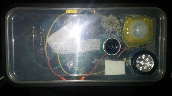
If you are interested in local wildlife, you may want to consider this wildlife camera project (Google cache). [Arnis] has been using his to film foxes and mice. The core components of this build are a Raspberry Pi and an infrared camera module specifically made for the Pi. The system runs on a 20,000 mAh battery, which [Arnis] claims results in around 18 hours of battery life.

[Arnis] appears to be using a passive infrared (PIR) sensor to detect motion. These sensors work by detecting sudden changes in the amount of ambient infrared radiation. Mammals are good sources of infrared radiation, so the sensor would work well to detect animals in the vicinity. The Pi is also hooked up to a secondary circuit consisting of a relay, a battery, and an infrared light. When it’s dark outside, [Arnis] can enable “night mode” which will turn on the infrared light. This provides some level of night vision for recording the furry critters in low light conditions.

[Arnis] is also using a Bluetooth dongle with the Pi in order to communicate with an Android phone. Using a custom Android app, he is able to connect back to the Pi and start the camera recording script. He can also use the app to sync the time on the Pi or download an updated image from the camera to ensure it is pointed in the right direction. Be sure to check out the demo video below.

If you like these wildlife cameras, you might want to check out some older projects that serve a similar purpose. Continue reading “Remote Controlled Wildlife Camera With Raspberry Pi”

Restoring A Vintage PDP-11/04 Computer

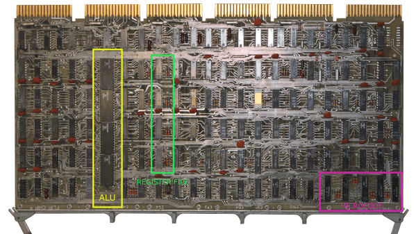
[MattisLind] spent one and a half years to complete restoration of a Digital Equipment Corporation (DEC) PDP-11/04 including peripherals like a TU60 tape drive and a LA30P Decwriter printing terminal. The computer is now able to run CAPS-11 which is a very simple operating system and also CAPS-11/BASIC. Just like the project itself, his blog post is quite long filled with interesting details. For a tl;dr version, check the video after the break.

This system originally belonged to Ericsson and [MattisLind] received it from Ericsson computer club, EDKX. He was lucky to have access to online resources which made the task easier. But it still wasn’t easy considering the number of hardware faults he had to tackle and the software challenges too. The first task was obviously looking at the Power supply. He changed the big electrolytic capacitors, and the power supply seemed to work well with his dummy load, but failed when hooked up to the backplane of the computer. Some more digging around, and a replaced thyristor later, he had it fixed. The thyristor was part of a crowbar circuit to protect the system from over-voltages should one of the main switching transistors fail.

With the power supply fixed, the CPU still wouldn’t boot. Some sleuthing around, and he pin pointed the bus receiver chip that had failed. His order of the device via a Chinese ebay seller was on the slow boat, so he just de-soldered a device from another board which improved things a bit, but it was still stuck in a loop. A replacement communications board and the system now passed diagnostics check, but failed memory testing. This turned out to be caused be a faulty DIP switch. He next tackled all the software challenges in getting the CPU board up to speed.

Continue reading “Restoring A Vintage PDP-11/04 Computer”

TFT Display

Controlling A Color TFT Display With PIC32

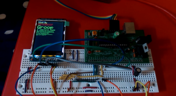
Sometimes it feels like everyone out there is using Arduino. It’s easy to find tutorials and libraries to get things working with Arduino, but if you want to use another platform you might have more trouble. [Tahmid] ran into this problem when he decided to try using a PIC32 to control a 2.2″ color TFT display from Adafruit.

Adafruit is really good about providing tutorials and Arduino libraries for their products. It makes it really easy to get up and running… if you are using Arduino. All of their libraries are open source, which means that the community can take them and modify them as needed. [Tahmid] decided to do exactly this and fork the Adafruit libraries over to the PIC32 platform in C. It’s a great learning experience. You get to see how (good or bad) other people code, and it immerses you in the differences between two different chip families.

He’s released the libraries online for others to use. He says that he’s heavily commented the code to try to make as self-explanatory as possible. The display interfaces with the PIC32 using SPI. The demo video below shows the screen up and running and demonstrates the crisp color graphics. Continue reading “Controlling A Color TFT Display With PIC32”

The Dan64: A Minimal Hardware AVR Microcomputer

[Juan] sent us his writeup of a microcomputer he built using an Arduino UNO (AVR ATmega328p) and some off-board SRAM. This one’s truly minimalistic.

Have a look at the schematics (PDF). There’s an Arduino, the SPI SRAM, some transistors for TV video output, and a PS/2 connector for the keyboard. That’s it, really. It’s easily built on a breadboard in a few minutes if you have the parts on hand. Flash the Dan64 operating system and virtual machine into the AVR and you’re good to go.

Now we’ve seen a few 6502-based retro computers around here lately that use a 6502 paired with a microcontroller for the interfacing, but they’ve all been bulky three-chip affairs. [Juan] wins the minimalism prize by using a 6502 virtual machine implemented in the AVR to reduce the parts count down to two chips for the whole shooting match.

Using a 6502 virtual machine was a crucial choice in the design, because there are 6502 cross compilers that will let you compile and debug code for the microcomputer on your macrocomputer and then load it into the micro to run. This makes developing for the micro less painful.

How does it load programs you ask? The old-fashioned way of course, using audio files. Although rather than using the Kansas City Standard as in days of yore, he encodes the data in short and long pulses of square waves. This might be less reliable, but it sure saves on external hardware.

Continue reading “The Dan64: A Minimal Hardware AVR Microcomputer”

How To Properly Crimp Electronics Connectors

Putting crimp connectors on wires is one of the most tedious things you’ll do. It’s not easy, either, unless you have some practice. Before you start digging in to a pile of connectors, crimp terminals, and wire, it’s a good idea to know what you’re getting into and Gogo:tronics has a great tutorial on how to crimp electronics connectors.

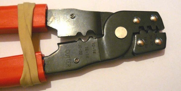
Crimping connectors onto wires requires the right tool, and the most important for this task is – surprise – the crimping pliers. These pliers press the crimping wings of the connector into each other, a task made much easier on the non-ratcheting pliers if you use a rubber band to hold the jaws of the crimping pliers open just enough to hold a crimp connector.

The general theory for crimping all types of connectors is to strip a little bit of insulation off the wire. Then, put the connector into a suitably sized space in the jaws, insert the wire, and crimp it down. For non-ratcheting pliers, it’s suggested the connector be re-crimped with the next smallest hole in the jaws.

There are a few connector-specific tips for the most common connector types, too. Dupont connectors – those flat, black connectors with a 0.1″ pitch – go together like you think they would, but for larger connectors – VH and XH-style – it’s important to use the right wire gauge and not to squish the square female part of the connector.

Retrotechtacular: The Bessemer Converter

Here’s a rose-colored look into the steelworks at Workington, Cumbria in northern England. At the time of filming in 1974, this plant had been manufacturing steel nonstop for 102 years using the Bessemer process. [Sir Henry Bessemer]’s method for turning pig iron into steel was a great boon to industry because it made production faster and more cost-effective.

hot ingotsMore importantly, [Bessemer]’s process resulted in steel that was ten times stronger than that made with the crucible-steel method. Basically, oxygen is blown through molten iron to burn out the impurities. The silicon and manganese burn first, adding more heat on top of what the oxygen brings. As the temperature rises to 1600°C, the converter gently rocks back and forth. From its mouth come showers of sparks and a flame that burns with an “eye-searing intensity”. Once the blow stage is complete, the steel is poured into ingot molds. The average ingot weighs four tons, although the largest mold holds six tons. The ingots are kept warm until they are made into rail.

The foreman explains that Workington Works would soon be switching over to a more modern process. As it was, Workington ran a pair of Bessemer converters on a 40-minute schedule, ensuring constant steel production from ore to rail. Between 1872 and 1974, these converters created an estimated 25 million metric tons of steel.

Continue reading “Retrotechtacular: The Bessemer Converter”