This $0 Filament Drybox Needs Nearly No Parts

All 3D printer filament benefits from being kept as dry as possible, but some are more sensitive to humidity than others. The best solution is a drybox; a sealed filament container, usually with some desiccant inside. But in a pinch, [Spacefan]’s quick and dirty $0 drybox solution is at least inspiring in terms of simplicity.

The only added part is this 3D-printed fitting.

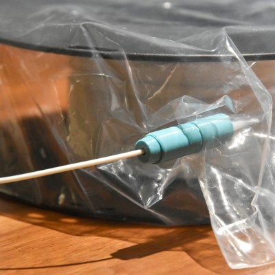
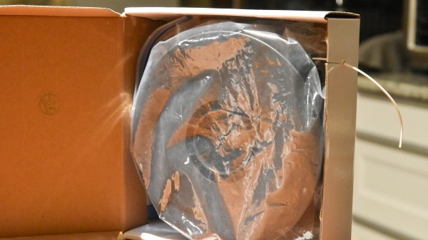
[Spacefan]’s solution uses a filament roll’s own packing materials and a single 3D-printed part to create a sealed environment for a single roll. The roll lives inside a plastic bag (potentially the same one it was sealed in) and filament exits through a small hole and 3D-printed fitting that also uses a bit of spare PTFE tubing. The box doubles as a convenient container for it all. It doesn’t have as much to offer as this other DIY drybox solution, but sure is simple.

While we appreciate the idea, this design is sure to put a lot of friction on the spool itself. It will be a lot of extra work to pull filament off the spool, which needs to turn inside a bag, inside a box, and that extra work will be done by the 3D printer’s extruder, a part that should ideally be working as little as possible. The re-use of materials is a great idea, but it does look to us like the idea could use some improvement.

What do you think? Useful in a pinch, or needs changes? Would adding a spindle to support the spool help? Let us know what you think in the comments.

Robot astronaut gazing at the moon

NASA’s New Moon Missions Are Happening Really Soon

NASA first landed a human on the moon back in 1969, and last achieved the feat in December 1972. In the intervening years, there have been few other missions to Earth’s primary natural satellite. A smattering of uncrewed craft have crashed into the surface, while a mere handful of missions have achieved a soft landing, with none successful from 1976 to 2013.

However, NASA aims to resume missions to the lunar surface, albeit in an uncrewed capacity at this stage. And you won’t have to wait very long, either. The world’s premier space agency aims to once again fly to the Moon beginning in February 2022.

Continue reading “NASA’s New Moon Missions Are Happening Really Soon”

Not Your Average Nixie Tube Clock

When it comes to Nixie clocks, we all pretty much know what to expect: a bunch of Nixies with some RGB LEDs underneath, a wooden case of some sort, and maybe some brass gears or fittings for that authentic steampunk look. It’s not that we don’t appreciate these builds, but the convergent designs can be a little much sometimes. Thankfully, this 60-tube Nixie clock bears that mold, and in a big way.

The key to [limpkin]’s design is the IN-9 Nixie, which is the long, skinny tube that used to show up as linear indicators; think bar graph displays on bench multimeters or the VU meters on mixing boards. [limpkin] realized that 60 on the tubes could be arranged radially to represent hours or minutes, and potentially so much more. The length of the segment that lights up in the IN-9 is controlled by the current through the tube, so [limpkin] designed a simple driver for each segment that takes a PWM signal as its input. The job of a 60-channel, 14-bit PWM controller fell to an FPGA. An ESP8266 — all the rage five years ago when he started the project — took care of timekeeping and control, as well as driving a more traditional clock display of four 7-segment LEDs in the center of the clock face.

The custom PCB lives in a CNC-machined MDF wood face; the IN-9s shine through slots in the face, while the seven-segment display shows through a thinned area. It looks pretty cool, and there are a lot of display options, like the audio spectrograph shown in the video below. We’re glad [limpkin] decided to share this one after all this time.

Continue reading “Not Your Average Nixie Tube Clock”

Teardown: Analog Radionic Analyzer

Have you ever looked up a recipe online, and before you got to the ingredients, you had to scroll through somebody’s meandering life story? You just want to know how many cans of tomato paste to buy, but instead you’re reading about cozy winter nights at grandma’s house? Well, that’s where you are right now, friend. Except instead of wanting to know what goes in a lasagna, you just want to see the inside of some weirdo alternative medicine gadget. I get it, and wouldn’t blame you for skipping ahead, but I would be remiss to start this month’s teardown without a bit of explanation as to how it came into my possession.

So if you’ll indulge me for a moment, I’ll tell you a story about an exceptionally generous patron, and the incredible wealth of sham medical hokum that they have bestowed upon the Hackaday community…

Continue reading “Teardown: Analog Radionic Analyzer”

Flip-Dot Oscilloscope Is Flippin’ Awesome

Oscilloscope displays have come a long way since the round phosphor-coated CRTs that adorned laboratories of old. Most modern scopes ship with huge, high-definition touch screens that, while beautiful, certainly lack a bit of the character that classic scopes brought to the bench. It’s a good thing that hackers like [bitluni] are around to help remedy this. His contribution takes the form of what may be both the world’s coolest and least useful oscilloscope: one with a flip-dot display.

Yup — a flip-dot display, in all it’s clickedy-clacky, 25×16 pixel glory. The scope can’t trigger, its maximum amplitude is only a couple of volts, and its refresh rate is, well, visible, but it looks incredible. The scope is controlled by an ESP32, which reads the analog signal being measured. It then displays the signal via an array of driver ICs, which allow it to update the dots one column at a time by powering the tiny electromagnets that flip over each colored panel.

Even better, [bitluni] live-streamed the entire build. That’s right, if you want to watch approximately 30 hours of video covering everything from first actuating a pixel on the display to designing and assembling a PCB to drive it, then you’re in luck. For the rest of us, he was kind enough to make a much shorter summary video you can watch below. Of course, this scope doesn’t run Doom like some others, but its probably only a matter of time.

Thank to [Zane Atkins] for the tip!

Continue reading “Flip-Dot Oscilloscope Is Flippin’ Awesome”

Development Of Magnetic Locking Idea Shows Great Progress

No matter how its done, with whatever level of fakery, magnetic levitation just looks cool.  We don’t know about you, but merely walking past the tackiest gadget shop, the displays of levitating and rotating objects always catches our eye. Superconductors aside, these devices are pretty much all operating in the same way; an object with a permanent rare-earth magnet is held in a stable position between a pair of electromagnets one above and one below, with some control electronics to adjust the field strength and close the loop.

But, there may be another way, albeit a rather special case, where a magnet can not only be levitated, but locked in place using a rotating magnetic field. The video shows a demonstration of how the mass of a magnet can be used to phase lock it against a rotating field. In essence, the magnet will want to rotate to align with the rotating magnetic field, but its mass will mean there is a time delay for the force to act and rotation to occur, which will lag the rotating magnetic field, and if it is phased just so, the rotation will be cancelled and the magnet will be locked in a stable position. Essentially the inertia of the magnet can be leveraged to counteract magnet’s tendency to rapidly rotate to find a stable position in the field.

Whilst the idea is not new, Turkish experimenter [Hamdi Ucar] has been working on this subject for some time (checkout his YouTube channel for a LOT of content on it), even going as far as to publish a very detailed academic paper on the subject. With our explanation here we’re trying to simplify the subject for the sake of brevity, but since the paper has a lot of gory details for the physicists among you, if you can handle the maths, you can come to your own conclusions.

Continue reading “Development Of Magnetic Locking Idea Shows Great Progress”

the conversion from hynix SRAM to FRAM on a Pokemon Yellow PCB

Pokemon Time Capsule

The precious Pokemon we spent hours capturing in the early nineties remain trapped, not just by pokeballs, but within a cartridge ravaged by time. Generally, Pokemon games before the GameBoy Advance era had SRAM and a small coin cell to save state as NVRAM (Non-volatile random access memory) was more expensive. These coin cells last 10-15 years, and many of the Pokemon games came out 20 years ago. [9943246367] decided to ditch the battery and swap the SRAM for a proper NVRAM on a Pokemon Yellow cartridge, 23 years later.

The magic that makes it work is a FRAM (ferroelectric random access memory) made by Cypress that is pin-compatible with the 256K SRAM (made by SK Hynix) on the original game cartridge PCB. While FRAM data will only last 10 years, it is a write-after-read process so as long as you load your save file every 10 years, you can keep your Pokemon going for decades. For stability, [9943246367] added a 10k pull-up on the inverted CE (chip enable) pin to make sure the FRAM is disabled when not in use. A quick test shows it works beautifully. Overall, a clever and easy to have to preserve your Pokemon properly.

Since you’re replacing the chip, you will lose the data if you haven’t already. Perhaps you can use [Selim’s] Pokemon Transporter to transport your pokemon safely from the SRAM to the FRAM.