A common joke in electronics is that every piece of wire and PCB trace is an antenna, with the only difference being whether this was intentional or not. In practical terms, low-frequency wiring is generally considered to be ‘safe’, while higher frequency circuits require special considerations, including impedance (Z) matching. Where the cut-off is between these two types of circuits is not entirely clear, however, with various rules-of-thumb in existence, as [Sebastian] over at Baltic Lab explains.
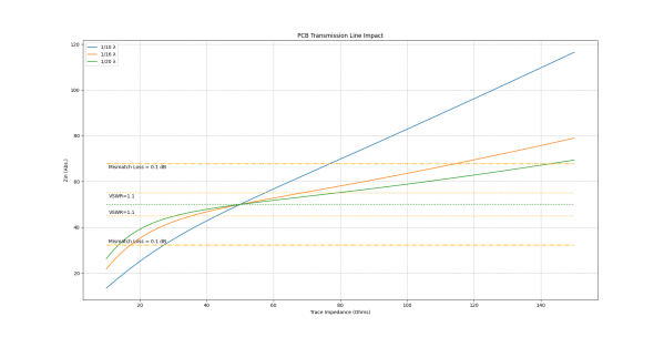
A popular rule is that no impedance matching between the trace and load is necessary if the critical length of a PCB trace (lcrit) is 1/10th of the wavelength (λ). Yet is this rule of thumb correct? Running through a number of calculations it’s obvious that the only case where the length of the PCB trace doesn’t matter is when trace and load impedance are matched.
According to these calculations, the 1/10 rule is not a great pick if your target is a mismatch loss of less than 0.1 dB, with 1/16 being a better rule. Making traces wider on the PCB can be advisable here, but ultimately you have to know what is best for your design, as each project has its own requirements. Even when the calculations look good, that’s no excuse to skip the measurement on the physical board, especially with how variable the dielectric constant of FR4 PCB material can be between different manufacturers and batches.
Heading image: Input impedance plotted as a function of trace impedance for trace lengths of 1/10, 1/16, and 1/20 of a wavelength. (Credit: Baltic Labs)
Continue reading “When Does Impedance Matching A PCB Trace Become Unavoidable?”

