
We preempt this week’s Hacklet to bring you an important announcement.
Hackaday.io got some major upgrades this week. Have you checked out The Feed lately? The Feed has been tweaked, tuned, and optimized, to show you activity on your projects, and from the hackers and projects you follow.
We’ve also rolled out Lists! Lists give you quick links to some of .io’s most exciting projects. The lists are curated by Hackaday staff. We’re just getting started on this feature, so there are only a few categories so far. Expect to see more in the coming days.
Have a suggestion for a list category? Want to see a new feature? Let us know!
Now back to your regularly scheduled Hacklet
There are plenty of cameras on Hackaday.io, from complex machine vision systems to pinhole cameras. We’re concentrating on the cameras whose primary mission is to create an image. It might be for art, for social documentation, or just a snapshot with friends.
 [theschlem] starts us off with Pinstax, a 3D Printed Instant Pinhole Camera. [theschlem] is using a commercial instant film camera back (the back for a cheap Diana F+) and 3D printing his own pinhole and shutter. He’s run into some trouble as Fuji’s instant film is fast, like ISO 800 fast. 3 stops of neutral density have come to the rescue in the form of an ND8 filter. Pinstax’s pinhole is currently 0.30mm in diameter. That translates to just about f/167. Nice!
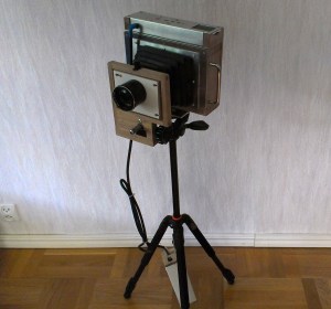
Next up is [Jimmy C Alzen] and his Large Format Camera. Like many large format professional cameras, [Jimmy’s] camera is designed around a mechanically scanned linear sensor. In this case, a TAOS TSL1412S. An Arduino Due runs the show, converting the analog output from the sensor to digital values, stepping the motor, and displaying images in progress on an LCD. Similar to other mechanically scanned cameras, this is no speed demon. Images in full sunlight take 2 minutes. Low light images can take up to an hour to acquire.
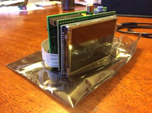 [Jason’s] Democracycam aims to use open source hardware to document protests – even if the camera is confiscated. A Raspberry Pi, Pi Cam module, and a 2.8″ LCD touchscreen make up the brunt of the hardware of the camera. Snapping an image saves it to the SD card, and uses forban to upload the images to any local peers. The code is in python, and easy to work with. [Jason] hopes to add a “panic mode” which causes the camera to constantly take and upload images – just in case the owner can’t.
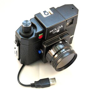 The venerable Raspberry Pi also helps out in [Kimondo’s] Digital Holga 120d. [Kimondo’s] fit a Raspberry Pi model A, and a Pi camera, into a Holga 120D case. He used the Slice of pi prototype board to add a GPIO for the shutter release button, a 4 position mode switch, and an optocoupler for a remote release. [Kimondo] even added a filter ring so he can replicate all those instagram-terrific filters in hardware. All he needs is to add a LiPo battery cell or two, a voltage regulator, and a micro USB socket for a fully portable solution.
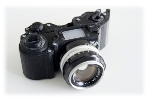
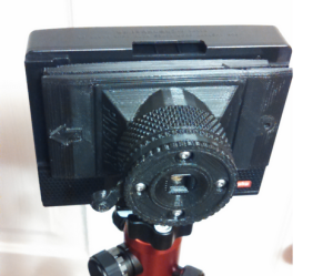
Finally, we have [LeoM’s] OpenReflex rework. OpenReflex is an open source 3D printed Single Lens Reflex (SLR) 35mm film camera. Ok, not every part is 3D printed. You still need a lens, a ground glass screen, and some other assorted parts. OpenReflex avoids the use of a pentaprism by utilizing a top screen, similar to many classic twin lens reflex cameras. OpenReflex is pretty good now, but [Leo] is working to make it easier to build and use. We may just have to break out those rolls of Kodachrome we’ve been saving for a sunny day.
That’s it for this week’s Hacklet! Until next week keep that film rolling and those solid state image sensors acquiring. We’ll keep bringing you the best of Hackaday.io!


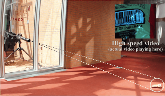
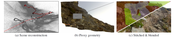 First person video – between Google Glass, GoPro, and other sports cameras, it seems like everyone has a camera on their head these days. If you’re a surfer or skydiver, that might make for some awesome footage. For the rest of us though, it means hours of boring video. The obvious way to fix this is time-lapse. Typically time-lapse throws frames away. Taking 1 of every 10 frames results in a 10x speed increase. Unfortunately, speeding up a head mounted camera often leads to a video so bouncy it can’t be watched without an air sickness bag handy. [Johannes Kopf], [Michael Cohen], and [Richard Szeliski] at Microsoft Research have come up with a novel solution to this problem with
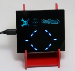
 In honor of DEFCON, this week we’re looking at some cryptography and reverse engineering projects over at Hackaday.io