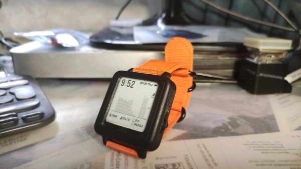
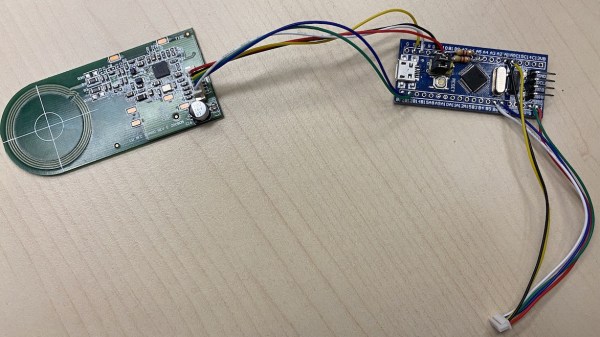
TshWatch is a project by [Ivan / @pikot] that he’s been working on for the past two years. [Ivan] explains that he aims to create a tool meant to help you understand your body’s state. Noticing when you’re stressed, when you haven’t moved for too long, when your body’s temperature is elevated compared to average values – and later, processing patterns in yourself that you might not be consciously aware of. These are far-reaching goals that commercial products only strive towards.
At a glance it might look like a fitness tracker-like watch, but it’s a sensor-packed logging and measurement wearable – with a beautiful E-Ink screen and a nice orange wristband, equipped with the specific features he needs, capturing the data he’d like to have captured and sending it to a server he owns, and teaching him a whole new world of hardware – the lessons that he shares with us. He takes us through the design process over these two years – now on the fifth revision, with first three revisions breadboarded, the fourth getting its own PCBs and E-Ink along with a, and the fifth now in the works, having received some CAD assistance for battery placement planning. At our request, he has shared some pictures of the recent PCBs, too!
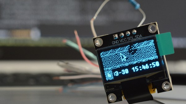
One day, [mitxela] got bored and decided to build his own HDMI monitor – the unconventional way. HDMI has a few high-speed differential pairs, but it also has an I2C interface used for detecting the monitor’s resolution and issuing commands like brightness control. In fact, I2C is the backbone for a lot of side channels like these – it’s also one of our preferred interfaces for connecting to cool sensors, and in this case, an OLED display!
[mitxela] describes his journey from start to end, with all the pitfalls and detours. Going through the pinout with a broken hence sacrificial HDMI cable in hand, he figured out how to probe the I2C lines with Linux command-line tools and used those to verify that the display was recognized on the HDMI-exposed I2C bus. Then, he turned to Python and wrote a short library for the display using the smbus bindings – and, after stumbling upon an FPS limitation caused by SMBus standard restrictions, rewrote his code to directly talk to the I2C device node, raising FPS from 2 to 5-10.
From there, question arose – what’s the best software route to take? He tried making a custom X modeline on the HDMI port the display was technically attached to, but that didn’t work out. In the end, he successfully employed the Linux capability called “virtual monitors”, and found out about an interesting peculiarity – there was no mouse cursor to be seen. Turns out, they’re typically hardware-accelerated and overlaid by our GPUs, but in [mitxela]’s case, the GPU was not involved, so he added cursor support to the picture forwarding code, too.
With partial refresh, the display could be redrawn even faster, but that’s where [mitxela] decided he’s reached a satisfactory conclusion to this journey. The write-up is a great read, and if videos are more your forte, he also made a video about it all – embedded below.
We first covered the ability to get I2C from display ports 14 years ago, and every now and then, this fun under-explored opportunity has been popping up in hackers’ projects. We’ve even seen ready-to-go breakouts for getting I2C out of VGA ports quickly. And if you go a bit further, with your I2C hacking skills, you can even strip HDCP!
We thank [sellicott] and [leo60228] for sharing this with us!
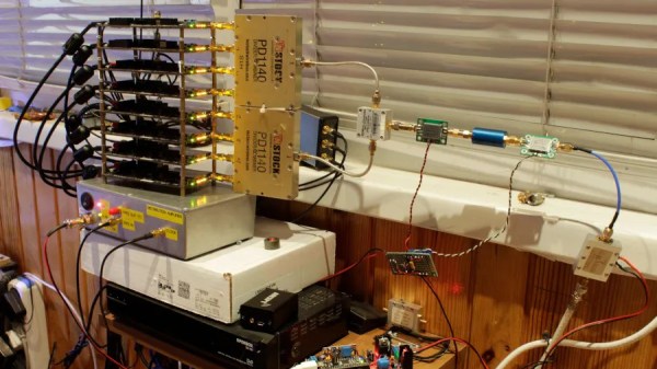
[Oleg Kutkov] decided to build a wideband SDR – for satellite communication research and monitoring, you know, the usual. He decided on a battery of HackRF boards – entire eight of them, in fact. Two 1×4 and one 1×2 RF splitters and an LNA on their combined RF input made for a good start to the project, and from there, it only got more complex.
HackRF boards can be synchronized with a separate clock source, but you can’t just pull a single clock line to all of them in a star configuration. Thus, he’s built a clock distribution and amplifier board, with 4 ns propagation delay at 1 PPS, and only 10 ns delay at 10 MHz. Then, he integrated that board with the HackRF setup, adding a case, wiring up a purpose-built cable and dealing with the reflections that occurred.
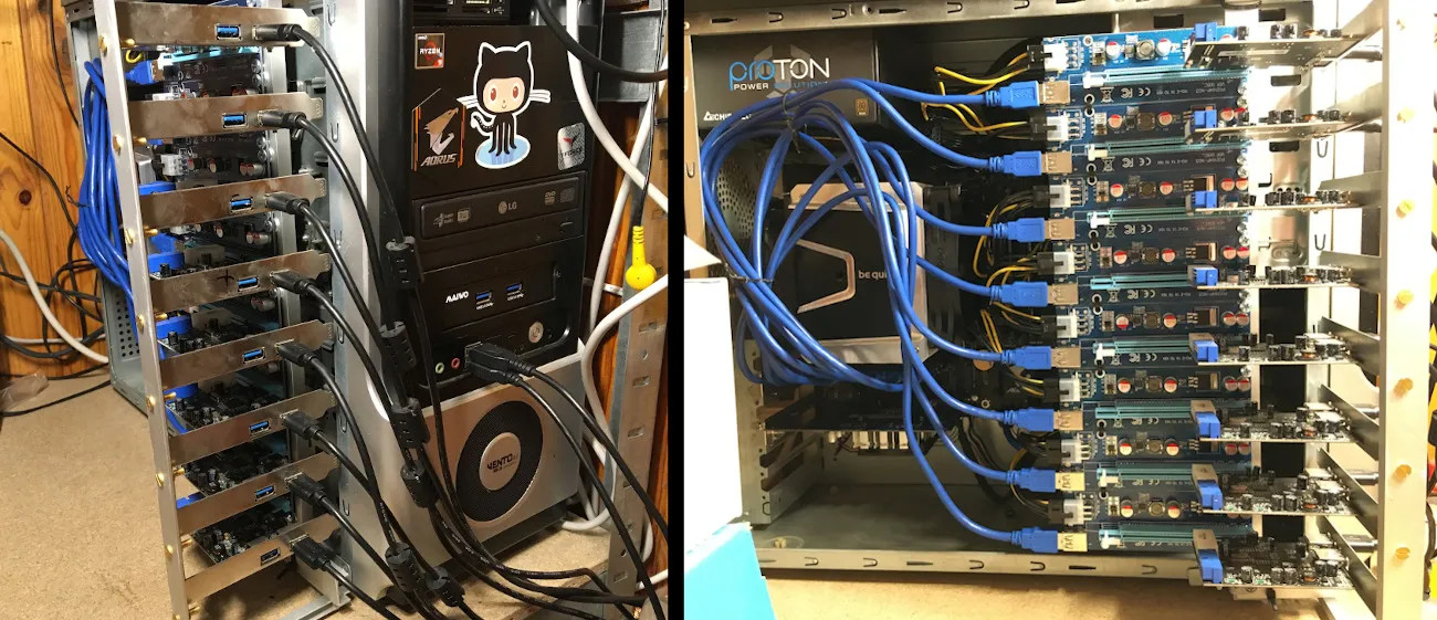
HackRF boards are USB 2.0 and able to generate a stream of data up to 320 MB/s, and there’d be no viable way to aggregate eight 2.0 links into one. To solve that, he’s used eight separate PCI-E to USB 3.0 cards, each of them with one HackRF plugged in, all connected to an AMD Ryzen 9-powered PC through PCI-E risers we typically see used for mining purposes. To tie it all together, he created a gnuradio flowgraph and patched the osmocom source block to enable the external clock synchronization mechanisms he decided to use.
Each HackRF is connected to its own PCIe USB card.
In the end, [Oleg] shows us some promising results – two DVB-S transceivers visible on the waterfall display of the spectrum capture. The work is not over here, to be clear – he’s ran into a few roadblocks. The gnuradio flowgraph doesn’t lend itself well to multi-threading, even on a Ryzen 9 machine, and [Oleg] pledged to rewrite the capture mechanisms in C++ which can be nicely allocated to separate physical CPU cores, something gnuradio is apparently not quite good at.
More importantly, the spectrum captured is not continuous, and [Oleg] questions whether it can be demodulated properly. He had to resort to frequency overlaps due to upsampling, and he’s not quite sure how to compensate for that. Overall frequency stability is also in question. However, from here, seems like most of the work towards building a wideband receiver is done!
[Oleg] is typically seen on Twitter, lately doing some heavy tinkering with Starlink – as Kyiv, the city he’s currently in, is under bombardment of Russian Armed Forces. We can only respect and appreciate the dedication. In January, we’ve covered his work on an USA-imported Tesla LTE modem replacement to fix LTE band incompatibilities in Ukraine, and his blog is a treasure trove of experiments that we are yet to properly comb through, from astrophysics and satellite work to RS485 networks and Linux driver writing.
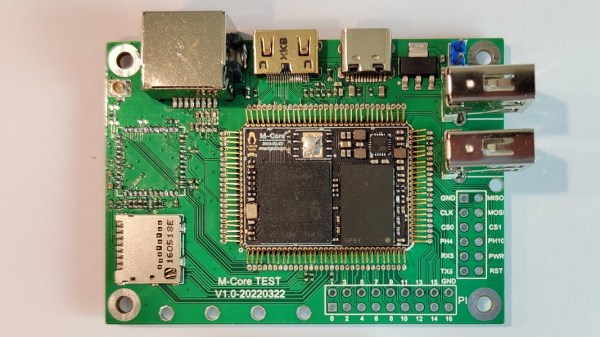
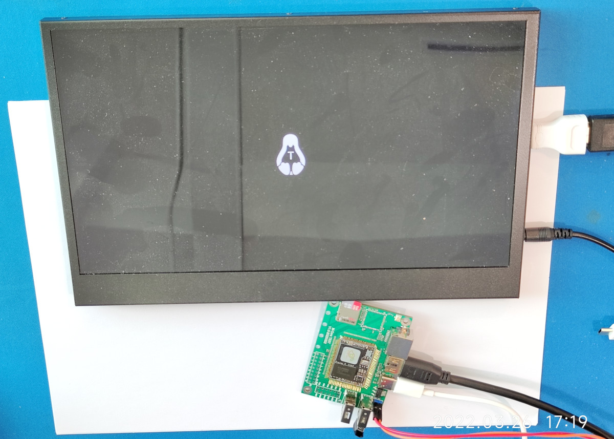
Today’s Diminutive Device is a small castellated System-On-Module (Twitter link, nitter proxy) from [MangoPi] called M-Core, with a quad-core A53 CPU and 1 GB of RAM. As such, it’s very capable of running Linux, and even sports an HDMI output! Taking a closer look at the devboard picture, we can spot traces for three USB 2.0 ports, what seems to be two SDIO interfaces for MicroSD or WiFi cards, and an Ethernet MagJack with its termination network. This is a decent set of interfaces, rivaling what we’d expect out of a Pi Zero!
More importantly, this module is as small as an SD card itself – or as an OLED display that we hobbyists sprinkle onto our projects. Having power of Linux in such a small footprint is certainly something to behold! The back of the module is mostly flat, save for a few decoupling capacitors on the other side of the CPU – it seems, an Allwinner H616. On top of it, we can see the CPU itself, a small buck regulator and a DDR3 RAM chip, as well as tightly-packed passives. There’s even an unpopulated footprint for a DFN8 QSPI flash chip – with a lightweight enough OS build, you could perhaps dedicate your MicroSD card to storage only.
The devboard for uses the “FlexyPins”-like connectivity technique we’ve covered recently, and [MangoPi] say they bought those pins on TaoBao. We can’t help but be a bit amused at the thought of putting HDMI through such connections, but it seems to work well enough! Castellated modules like these are relatively easy to work with, so it shouldn’t be hard to literally pop this module out of the devboard and figuratively pop it onto your PCB. Next step is, reportedly, porting Armbian to this board, likely solving quite a few software support hurdles.
MangoPi have been posting updates on their Twitter page over the last few weeks, and, as it comes with the format, a lot of questions are left unanswered. Why does the devboard only show a single linear regulator of the kind we typically expect to deliver 1 A at most? Will we get higher-RAM versions? What’s the price going to look like? Will this module ever get to market? We can only hope, but if it does indeed, we are sure to see a few projects with these, whether it’s smart glasses, smart displays, phones, handhelds or malicious wall chargers. As usual, community makes or breaks an SBC, and we shall watch this one closely.
We thank [WifiCable] and [DjBiohazard] for sharing this with us!
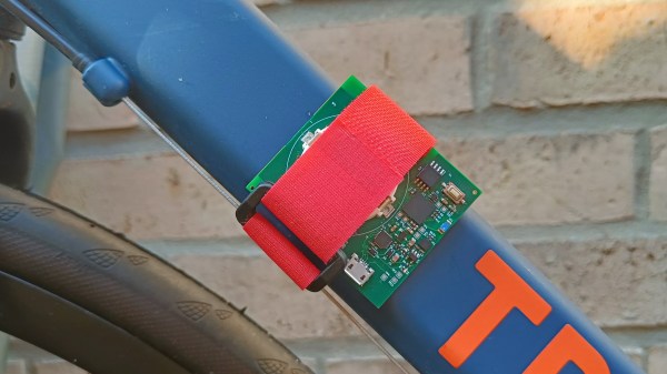
[elektroThing] is building a lightweight, battery-powered board to track and measure movement of all kinds, called Tracer. Powered by an ESP32, it has a LSM6DSL 6DoF accelerometer & gyroscope sensor, and a VL53L0X Time-of-Flight sensor. A small Li-ion battery in a holder reportedly provides for 5 hours of streaming data over Bluetooth Low Energy (BLE) at 100 Hz. It’s essentially a wireless movement sensor platform to be paired with a more powerful computer for data logging and analysis. What’s such a platform good for?
They show it attached to a tennis racket, saying you could use the data to, for a start, count the strokes done in a given match. They’ve also strapped it to a bicycle’s crankshaft and used it as a cadence sensor – good for gauging your cycling efficiency! But of course, this can be used in more applications than sport. A device like this could be used for logging movement of any relatively nearby objects, be it your cat, an office chair, or a door someone might slam a bit too hard at times. Say, you wanted to develop a sleep tracker and were to collect some data for defining your algorithms and planning your hardware requirements – this would work wonders.
There’s already available example code for streaming data into the Phyphox data logging and graphing app, as well as schematics – hopefully, the full board files will be available soon. A worthy open-source opponent to commercial devices available for similar purposes, this platform is good news for any hacker that wants to do motion measurement projects without reinventing quite a few wheels at once. We are told this board might get to CrowdSupply soon, and we can’t wait! Platforms like these, if done well, can grow an offspring of new projects for us to have fun with, and our paid projects get all that much easier to work on.
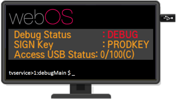
One boring evening, [XenRE] was looking through service menus on their LG Smart TV (Russian, Google Translate), such menus accessible through use of undocumented IR remote codes. In other words, a fairly regular evening. They noticed an “Access USB Status” entry and thought the “Access USB” part looked peculiar. A few service manuals hinted that there’s a service mode you could access with an adapter made out of two back-to-back PL2303 USB-UART adapters – a few female-female jumper wires later, serial prompt greeted our hacker, and entering ‘debug’ into the prompt responded with some text, among it, “Access USB is NOT opened!!!”.
[XenRE] found the WebOS firmware for the TV online, encrypted and compressed into a proprietary LG .epk format, but liberated with an open-source tool. A few modules referred to AccessUSB there, and one detour into investigating and explaining WebOS USB vendor lock-in implementation later, they programmed an STM32 with the same VID and PID as the mythical AccessUSB device found in relevant WebOS modules decompiled with IDA. By this point, AccessUSB could safely be assumed to be a service mode dongle. The TV didn’t quite start beeping in a different pattern as we’d expect in a sci-fi movie, but it did notify about a “new USB device” – and started asking for a 6-symbol service menu password instead of a 4-symbol one. Continue reading “What’s That AccessUSB Menu In My LG SmartTV?”→
DYMO 550 series printer marketing blurb says “The DYMO® LabelWriter® 550 Turbo label printer comes with unique Automatic Label Recognition™”, which, once translated from marketing-ese, means “this printer has DRM in its goshdarn thermal stickers”. Yes, DRM in the stickers that you typically buy in generic rolls. [FREEPDK] didn’t like that, either, and documents a #FreeDMO device to rid us of yet another consumer freedom limitation, the true hacker way.
The generic BluePill board and two resistors are all you need, and a few extra cables make the install clean and reversible – you could definitely solder to the DYMO printer’s PCBs if you needed, too. Essentially, you intercept the RFID reader connections, where the BluePill acts as an I2C peripheral and a controller at the same time, forwarding the data from an RFID reader and modifying it – but it can also absolutely emulate a predetermined label and skip the reader altogether. If you can benefit from this project’s discoveries, you should also take a bit of your time and, with help of your Android NFC-enabled phone, share your cartridge data in a separate repository to make thwarting future DRM improvements easier for all of us. Continue reading “#FreeDMO Gets Rid Of DYMO Label Printer DRM”→