Towards A Tiny Pick And Place Head

One of the projects that has been on [Peter Jansen]’s build list for a long time – besides a fully functioning tricorder, of course – is a pick and place machine. It’s a project born out of necessity; each tricorder takes four days to assemble, and assembling the motherboard takes eight hours with a soldering iron and hot air gun. The pick and place machine isn’t complete yet, but one vital component – the vacuum head for picking up components – is getting there with the help of some odd components.

A few months ago, [Peter] saw a post on Hackaday about repurposing a tiny piezo micro blower for use as an extremely small vacuum pen. The original build was extremely simple – just a few pieces of foam board and a power supply, but the potential was there. A tiny electric air pump that’s able to pick up large chips and modules along with tiny resistors without having to run a hose through the mechanics of a CNC gantry is a godsend.

[Peter] got his hands on one of these micro blowers and started work on a proper tool head for a pick and place machine. A port on the micro blower was covered so it would suck instead of blow, the vacuum port was threaded through a stepper motor with a hollow shaft, and a fine tip was attached to the end.

What can this vacuum head pick up? 0604 size resistors aren’t a problem, but larger modules are simply too heavy. It looks like this micro blower would only be able to pick up small components. There are other options, though: [Grant Trebbin] has had some luck with a larger pump from Sparkfun, but this requires a vacuum line to run through a CNC gantry. There’s still some work to do before a small vacuum head shows up on the tool head of a pick and place machine, but given how long it takes [Peter] to put together a single tricorder, it’s well worth investing the time to do this right.

Reproducing A DSKY

This is a project that is about a year and a half in the making, but [Fran] is finally digging into the most iconic part of the Apollo Guidance Computer and building the most accurate reproduction DSKY ever.

The Apollo Guidance Computer was a masterpiece of engineering and is frequently cited as the beginning of the computer revolution, but it didn’t really look that interesting – it looks like a vastly overbuilt server blade, really. When everyone thinks about the Apollo Guidance Computer, they think about the DSKY, the glowey keypad interface seen in the blockbuster hit Apollo 13 and the oddly accurate disappointment of Apollo 18. It’s the part of the Apollo Guidance Computer the Apollo astronauts actually interacted with, and has become the icon of the strange, early digital computers developed for NASA in the 60s.

There are a few modern DSKY replicas, but all of them are exceedingly anachronistic; all of these reproductions use seven-segment LEDs, something that didn’t exist in the 1960s. A true reproduction DSKY would use custom electroluminescent displays. These EL segments are powered by AC, and transistors back then were terrible, leading to another design choice – those EL segments were turned on and off by relays. It’s all completely crazy, and aerospace equipment to boot.

Because of the custom design and engineering choices that seem insane to the modern eye, there isn’t much in the way of documentation when it comes to making a reproduction DSKY. This is where [Fran] tapped a few of the contacts her historical deconstruction cred earned when she reverse engineered a Saturn V Launch Vehicle Digital Computer to call upon anyone who would have access to a real Apollo-era DSKY.

The first contact was the Kansas Cosmosphere who was kind enough to send extremely detailed photographs of the DSKYs in their archives. It would have been extremely nice to have old documentation made when the DSKYs were rolling off the assembly line, but that information is locked away in a file cabinet owned by Raytheon.

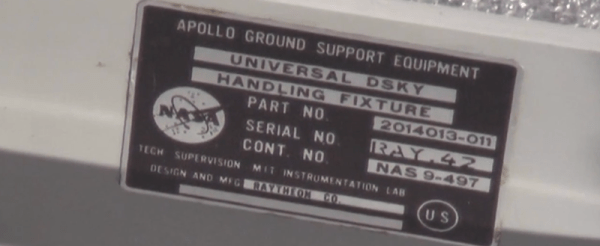
[Fran] got a break when she was contacted by curators at the National Air and Space Museum’s Garber facility who invited her down to DC. She was given the grand tour, including the most elusive aircraft in the museum’s collection, the Ho 229, the dual-turbojet Nazi flying wing. At the Garber facility, [Fran] received permission to take apart two DSKYs.

The main focus of [Fran]’s expedition to the Air and Space Museum was to figure out how the EL displays were constructed. The EL displays that exist today are completely transparent when turned off because of the development of transparent conductors.

The EL displays in the DSKY were based on earlier night lights manufactured by Sylvania. After looking at a few interesting items that included Gemini hardware and early DSKYs, this sort of construction was confirmed.

With a lot of pictures, a lot of measurements, a lot of CAD work, and some extremely tedious work, [Fran] was able to create the definitive reference for DSKY display elements. There are 154 separate switchable element in the display, all controlled by relays. These elements are not multiplexed; every element can be turned on and off individually.

Figuring out how the elements were put together was only one part of [Fran]’s research. Another goal was to figure out the electrical connections between the display and the rest of the DSKY. There, [Fran] found 160 gold pins in a custom socket. It’s bizarre, and more like a PGA socket than like the backplane connector [Fran] found in the Saturn V computer.

Even though [Fran]’s research was mostly on the EL panel inside the display, she did get a few more insights with her time with the DSKYs. The buttons are fantastic, and the best keys she’d ever used. This is just part one of what will be an incredibly involved project, and we’re looking forward to what [Fran] looks into next.

The Teensy LC. LC Means Low Cost.

For one reason or another, we’ve been seeing a lot of builds featuring the Teensy 3.1 filtering in on the tip line recently. In retrospect, it’s somewhat obvious; it’s a good board that’s cheap and fast. Yes, somehow [Paul] hit all three in the good/cheap/fast mutually exclusive triumvirate.

Now, there’s a new Teensy. It’s the Teensy LC – Low Cost. It’s not as powerful as the Teensy 3.1, but it does give you the power of an ARM for something that’s just about as cheap as a board with an ATMega.

The chip [Paul] chose for the Teensy LC is the Freescale MKL26Z64 (datasheet here and 876-page reference manual here. PDFs of course). This is a 32-bit Cortex-M0+ running at 48 MHz with 64k of Flash and 8k of RAM. There are 27 digital I/O pins on this one, and the Teensy LC has been designed to be pin-compatible with the Teensy 3.0 and 3.1.

On board are 13 analog inputs, 8 PWM outputs, on 12-bit DAC output, three serial ports, two SPI ports, and two I2C ports. Most of the pins can drive 5mA with a few capable of driving 20mA, and there is a single 5v output pin for driving WS2812 Neopixel LEDs.

Since this is a cut-down version of the Teensy, everything available on the Teensy 3.1 just can’t fit into the BOM of the Teensy LC. The pins aren’t 5V tolerant, there’s no CAN bus, and there are only 4 DMA channels instead of 16 on the Teensy 3.1. Still, it’s a great ARM answer to the ATMega Trinket or other small dev boards.

How Fast Is Your Flash?

What’s cooler than learning about timers and interrupts on AVRs? Well, if you’re like [Matt], you can use that learning experience to build something useful – in this case, a timer for various camera flashes.

There are two ways to measure the speed of a flash. The first is the lag between when a button is pressed and when the flash goes off. As long as this is consistent, everything’s okay. The second type of speed is the pulse width. When looking at a xenon flash as time vs. brightness, they have a large spike at the beginning followed by a significant amount of decay. LED flashes are pretty much one cycle of a square wave.

To measure both types of flash speed, [Matt] used a $0.50 photodiode an a 3.5mm jack that ties into the flash remote. These bits are wired up to an Arduino, a little bit of fun work with timers and interrupts happens, and [Matt] learns how fast his flash is.

Tubes On A Chip

The tubes you’ll find in guitar amps and high-end stereos were first designed in the 30s and 40s, and when you get to really, really advanced tube technology you’d be looking at extremely small tubes made in the 70s for military applications. For 40 years, there really haven’t been many advances in tube technology. Now, at last, there’s something new.

The Nutube 6P1, as this curious invention is called, is a full triode or half of a 12ax7 you’ll find in just about every tube amp ever. Unlike the 12ax7, it consumes 2% of the power required of a normal tube, is 30% of the size of the normal tube, and lasts for 30,000 hours.

This new tube-chip thing was brought to life by Korg, makers of fine musical equipment and Noritake Co., manufacturers of vacuum fluorescent displays. There’s no word on what these tubes will be used in and there’s no data sheet. There will be further announcements this year, so don your speculation spectacles and head to the comments.

REFLOW CHÂTEAU

[Will] had a few reasons for turning a toaster oven into a reflow oven – he needed a project for an ECE lab, the lab’s current reflow oven was terrible, and the man is trying to keep [Will] down by not allowing toaster ovens in dorm rooms. What was born out of necessity actually turned into a great project – a reflow oven with touchscreen controls.

The toaster oven used for this build is a model [Will] picked up at Sears. It’s actually pretty unique, advertised as a ‘digital toaster’. This isn’t marketing speak – there’s actually a thermistor in there, and the stock toaster is closed loop. After disassembling the toaster and getting rid of the guts, [Will] whipped up a PCB for a Teensy 3.1 and the Adafruit capacative touch shield.

With the Teensy and touch screen, [Will] came up with an interface that looks ten times better than anything you would find on a Chinese auction site. It’s a great build, and since it’s kept in the electronics lab, will certainly see a lot of use.

Introducing The Raspberry Pi 2

TL;DR It’s called the Raspberry Pi 2 Model B. Quad core ARM Cortex A7 with one Gig of RAM. It’s the same form factor as the Raspberry Pi Model B+. Available now at Newark, Element 14, Allied, and RS Components. It’s the same price as the old one. You’re not a child and you should learn to read.


The original Raspberry Pi released, three years ago, was looking a bit long in the tooth when it was first launched. That’s to be expected for a computer that sells for $35 USD. Three years is a long time in the world of electronics, and the Pi is due for an update. It’s here, now, and the biggest change is a faster quad-core chip, a better processor architecture, and 1GB of RAM.

The Raspberry Pi 2 Model B features a quad-core ARM Cortex A7 running at 1GHz with 1GB of RAM. This chip uses the ARMv7 architecture instead of the ARMv6 of the original Raspi. When playing around with it, it was noticeably zippier than my months-old Raspi Model B in web browsing tasks. Very, very cool, and something that opens up a few doors for CPU-intensive applications.

Although the CPU has been updated, there isn’t much else on the Pi that has changed. USB and Ethernet is still handled by the LAN9514 USB/Ethernet controller. If you’re looking for Gigabit Ethernet, sorry that’s not going to happen. We’re not going to get eMMC Flash, SATA ports, or anything groundbreaking other than the CPU with this hardware update. It’s pretty much just a CPU and RAM upgrade.

All the original ports found on the Raspberry Pi Model B+ are found on the Raspi 2; HDMI, audio, analog video, Ethernet, USB, CSI, the as-for-now unused DSI, and GPIO ports haven’t changed. Again, we’re looking at a CPU and RAM upgrade with this hardware release.

Instead of the odd Package On Package CPU and RAM stack featured in previous Raspberry Pis, the RAM has now moved to the back on the Raspi 2:

raspiback

The RAM chip is an Elpida EDB8132B4PB-8D-F, an eight gigabit DDR2 RAM that has the same clock rate as the RAM in the original Raspi. Don’t look for an increase in memory performance or speed. Instead, just be glad there’s now a full gigabyte of RAM on the Raspi.

A few of you may remember the ‘upgrade’ all those Raspberry Pi early adopters missed out on. After the first few hundred thousand Raspberry Pi Model Bs shipped, someone realized they could upgrade the RAM from 256 MB to 512 MB. It is not yet known whether the Raspberry Pi 2 will be upgraded as easily. Sixteen gigabit RAMs do exist, but now that the CPU and RAM aren’t on the same package, there’s more to consider than just plopping down a new RAM chip.

Continue reading “Introducing The Raspberry Pi 2”