Grinding A Bicycle Crank For Power Analysis

For [Mark] and [Brian]’s final project for [Bruce Land]’s ECE class at Cornell, they decided to replicate a commercial product. It’s a dashboard for a bicycle that displays distance, cadence, speed, and the power being generated by the cyclist. Computing distance, cadence and speed is pretty easy, but calculating power is another matter entirely.

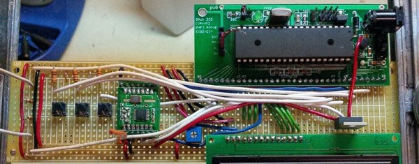
The guys are using an ATMega1284 to drive an LCD, listen in on some Hall Effect sensors, and do a few calculations. That takes care of measuring everything except power. A quick search of relevant intellectual property gave then the idea of measuring torque at the pedal crank. For that, [Mark] and [Brian] are using a strain gauge on a pedal crank, carefully modified to be stiff enough to work, but flexible enough to measure.

A custom board was constructed for the pedal crank that measures a strain gauge and sends the measurements through a wireless connection to the rest of the bicycle dashboard. It works, and the measurements in the classroom show [Brian] is generating about 450 W when pedaling at 33 mph.

Video below.

Continue reading “Grinding A Bicycle Crank For Power Analysis”

Flashing The ESP8266 In Windows

It’s only been a few months since the ESP8266 rolled out of some factory in China, and already the community is moving from simply getting custom firmware to work on the device to making the development tools easy to use. That’s huge – the barrier to entry is lowered, getting even more people on board with this very cool Internet of Things thing.

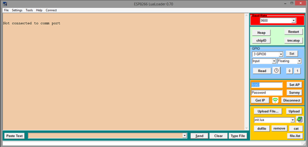
While the majority of the community is settling on using the Lua interpreter firmware, there’s still the matter of getting this firmware uploaded to the ESP. [Peter Jennings] of Microchess fame has been working on a Windows app to upload firmware to the ESP via a serial interface. There’s not much to it, but this will allow you to upload the community-created Lua firmware, set the WiFi credentials, toggle GPIO pins, and give you the ability to write a little bit of Lua in the same window.

If you’re looking for something that isn’t designed exclusively for Windows, there’s an alternative firmware flasher over on the nodemcu Github. This flasher also connects the ESP8266 to a network and uploads firmware. It’s a stripped-down programmer without a serial terminal or the ability to toggle pins, but there are plans for making this programmer cross-platform.

Running Doom On The Intel Edison

A few months ago, the Intel Edison launched with the promise of putting a complete x86 system on a board the size of an SD card. This inevitably led to comparisons of other, ARM-based single board computers and the fact that the Edison doesn’t have a video output, Ethernet, or GPIO pins on a 0.100″ grid. Ethernet and easy breakout is another matter entirely but [Lutz] did manage to give the Edison a proper display, allowing him to run Doom at about the same speed as a 486 did back in the day.

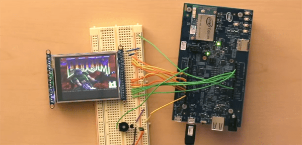
The hardware used for the build is an Edison, an Arduino breakout board, Adafruit display, speaker, and PS4 controller. By far the hardest part of this build was writing a display driver for the Edison. The starting point for this was Adafruit’s guide for the display, but the pin mapping of the Edison proved troublesome. Ideally, the display should be sent 16 bits at a time, but only eight bits are exposed on the breakout board. Not that it mattered; the Edison doesn’t have 16 pins in a single 32-bit memory register anyway. The solution of writing eight bits at a time to the display means Doom runs at about 15 frames per second. Not great, but more than enough to be playable.

For sound, [Lutz] used PWM running at 100kHz. It works, and with a tiny speaker it’s good enough. Control is through Bluetooth with a PS4 controller, and the setup worked as it should. The end result is more of a proof of concept, but it’s fairly easy to see how the Edison can be used as a complete system with video, sound, and wireless networking. It’s not great, but if you want high performance, you probably won’t be picking a board the size of an SD card.

Video demo below.

Continue reading “Running Doom On The Intel Edison”

A New Handle For An Old Soldering Station

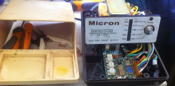
About 20 years ago, [Simon] spent a few week’s pay on a soldering station, a Micron W/2172. It served him well for the past few decades, but lately he hasn’t been able to find a supply of new tips for it. The Micron went into a cupboard and he upgraded to a newer Hakko soldering station.

The old Micron was still sitting in the cupboard when [Simon] realized both stations use a 24V supply for the heater, and you can buy replacement Hakko handle for a few bucks. Having two soldering stations would be handy, so [Simon] set out to convert the old Micron station to accept Hakko handles.

The only technical challenge for this modification was to figure out how the old circuit board in the Micron would read the thermistor  in the new handle. The original circuit used a dual op-amp, with one side used to amplify the thermocouple and the other to compare it to the temperature set point. After measuring the set point and a bit of Excel, [Simon] had a small circuit board that would replace the old op-amp. After that it was only a matter of wiring the new handle into the old station, calibrating the temperature settings, and enjoying the utility of two soldering stations.

Dual Complementary Optoisolator Logic

You’ve seen CMOS logic, you’ve seen diode-resistor logic, you’ve seen logic based on relays, and some of you who can actually read have heard about rod logic. [Julian] has just invented optoisolator logic. He has proposed two reasons why this hasn’t been done before: either [Julian] is exceedingly clever, or optoisolator logic is a very stupid idea. It might just be the former.

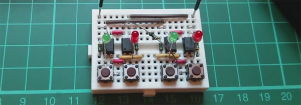
Inside each optoisolator is a LED and a phototransistor. There’s no electrical connection between the two devices, which is exactly what you need in something that’s called an isolator. [Julian] was playing around with some optoisolators one day to create a weird push-pull circuit; the emitter of one phototransistor was connected to the collector of another. Tying the other ends of the phototransistor to +5V and Gnd meant he could switch between VCC and VDD, with every other part of the circuit isolated. This idea whirled around his mind for a few months until he got the idea of connecting even more LEDs to the inputs of the optoisolators. He could then connect the inputs of the isolators to +5V and Gnd because of the voltage drop of four LEDs.

A few more wheels turned in [Julian]’s head, and he decided to connect a switch between the two optoisolators. Connecting the ‘input’ of the circuit to ground made the LED connected to +5V light up. Connecting the input of the circuit to +5 made the LED connected to ground light up. And deeper down the rabbit hole goes [Julian].

With a few more buttons and LEDs, [Julian] created something that is either an AND, NAND, OR NOR, depending on your point of view. He already has an inverter and a few dozen more optoisolators coming from China.

It is theoretically possible to build something that could be called a computer with this, but that would do the unique properties of this circuit a disservice. In addition to a basic “1” and “0” logic state, these gates can also be configured for a tri-state input and output. This is huge; there are only two universal gates when you’re only dealing with 1s and 0s. There are about 20 universal logic gates if you can deal with a two.

It’s not a ternary computer yet (although we have seen those), but it is very cool and most probably not stupid.

Video below.

Continue reading “Dual Complementary Optoisolator Logic”

Putting Lightning In Acrylic

Some folks at the i3Detroit hackerspace had an opportunity come up that would allow them to capture lightning in acrylic. They created a few Lichtenberg figures thanks to the help of a plastic tubing manufacturer, some lead sheet and a bunch of 1/2″ thick acrylic.

Lichtenberg figures are the 3D electrical trees found in paperweights the world over. They’re created through electrical discharge through an insulator, with lightning being the most impressive Lichtenberg figure anyone has ever seen. These figures can be formed in smaller objet d’art, the only necessity being a huge quantity of electrons pumped into the insulator.

This was found at Mercury Plastics’ Neo-Beam facility, a 5MeV electron accelerator that’s usually used to deliver energy for molecular cross linking in PEX tubing to enhance chemical resistance. For one day, some of the folks at i3Detroit were able to take over the line, shuffling a thousand or so acrylic parts through the machine to create Lichtenberg figures.

When the acrylic goes through the electron accelerator, they’re loaded up with a charge trapped inside. A quick mechanical shock discharges the acrylic, creating beautiful tree-like figures embedded in the plastic. There are a lot of pictures of the finished figures in a gallery, but if you want to see something really cool, a lead-shielded GoPro was also run through the electron accelerator. You can check out that video below.

Continue reading “Putting Lightning In Acrylic”

Using The Wink Hub With OpenHAB

Spend enough time looking at home automation setups, and you’ll quickly find there are two competing philosophies. The first wants to put an Arduino on every light socket, with everything connected by cheap eBay radio modules. The second home automation philosophy requires astonishingly expensive hardware to talk to other expensive modules. The Arduino solution is a system that can be infinitely customizable, and the commercial solution talks to ‘the cloud’ for some strange reason. There is no middle ground. At least there wasn’t until [Eric] started poking around and looked at a few hardware solutions.

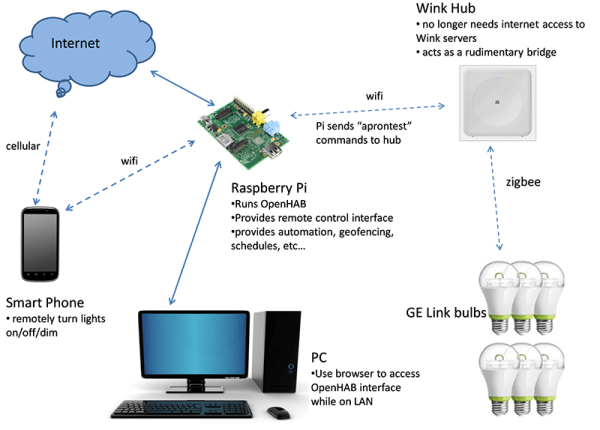
[Eric] was looking to control some GE Link bulbs through his phone, computer, or through the Internet. They’re supposed to be the best bulb on the market in terms of price and performance, but they can only be controlled with a Zigbee. This lead [Eric] to an interesting hack that gave all owners of the Wink Hub local control of their devices. From [Eric]’s research, this was the only way his lighting wasn’t dependent on ‘the cloud’.

Local control of the Wink was only possible after [Eric] read a post on rooting the Wink (and this post from a few days ago). Because the device could be rooted, and the fact that [Eric] already has a few things in his house integrated with OpenHAB, the choice on how to proceed with controlling a few Zigbee enabled lights was easy.

Once [Eric] got the light bulbs talking to the Wink, integrating them with the rest of the devices in his home was easy. The new bulbs are activated with his Arduino motion sensors, door sensors, and can be controlled via smartphone or by voice control. The Wink can also be completely disconnected from the Internet. A good idea, because the ability to turn a light on and off should not be dictated by the quality of your Internet connection.

Continue reading “Using The Wink Hub With OpenHAB”