Upgrading DJI Flight Controllers

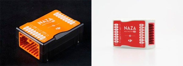
DJI, the company that gave us the far too popular Phantom line of quadcopters, doesn’t just make the most popular line of FPV quads. Their top of the line flight controller, The Naza V2, is very good, able to connect to flight planning software that will set waypoints, talk to peripherals over a CAN bus, and has improved flight algorithms. On the other hand, their ‘reduced price’ model, the Naza Light, can’t connect to these nifty CAN bus peripherals and has a bit of a problem with drifting the quad from one side or another.

The Naza V2 sells for around $300, and the Naza Light sells for about $170, both with a GPS module. The hardware inside the V2 and Light is exactly the same. We all know how this is going to go down, right?

[udnham] over on the RC Groups forum figured out a way to load the more capable Naza V2 firmware on the Naza Light, giving the cheaper flight controller features that were, until now, only found in the more expensive V2 hardware. The upgrades include better algorithms for GPS position and altitude hold, the ability to connect to DJI peripherals including the Bluetooth module, the iOSD, and camera gimbals, Octocopter support, the DJI datalink modem, and a bunch of other features.

Even though DJI is using the same hardware in the $170 Naza Light and the $300 Naza V2, upgrading the firmware requires an Internet connection to the DJI servers. [udnham] wrote a utility that modifies the /etc/hosts file on your computer, runs a service, and allows you to upgrade your firmware on the Naza Light. It’s basically a $130 firmware upgrade for a DJI flight controller that’s a single download away.

[udnham] set up a site where you can download the firmware flashing tool with a few videos showing the upgrade process and the improvement over the stock firmware. You can check those out below.

Continue reading “Upgrading DJI Flight Controllers”

800 X 600 VGA With The STM32F4

Generating VGA is a perennial favorite on the Hackaday tips line, and it’s not hard to see why. Low-res video games, of course, but sending all those pixels out to a screen is actually a pretty challenging feat of coding. The best most project have attained is the original VGA standard, 640×480. Now that we have fast ARMs sitting around, we can bump that up to 800×600, like [Karl] did with an STM32F4 Discovery board.

The problem with generating VGA on a microcontroller is the pixel frequency – the speed at which pixels are shoved out of the microcontroller and onto the screen. For an 800×600 display, that’s 36 MHz; faster than what the 8-bit micros can do, but a piece of cake for the STM32F4 [Karl] is using.

[Karl] started his build by looking at the VGA project Artekit put together. It too uses an STM32, but a 36-pin F103 part. Still, it was fast enough to generate a line-doubled 800×600 display. [Karl] took this code and ported it over to the F4 part on the Discovery board that has enough space for a full 800×600 frame buffer.

With all that RAM on board the F4 part, [Karl] was able to expand the frame buffer and create a relatively high-resolution display with DMA and about a dozen lines of code. It looks great, and now we just need a proper application for high-resolution VGA displays. Retrocomputing? A high-resolution terminal emulator? Who knows, but it’s a great use for the STM32.

If circles and some text aren’t your thing, Artekit also has Space Invaders running on the 36-pin STM32.

Digital To Analog To Digital To Analog To Digital Conversion

[Andy] had the idea of turning a mixing desk into a MIDI controller. At first glance, this idea seems extremely practical – mixers are a great way to get a lot of dials and faders in a cheap, compact, and robust enclosure. Exactly how you turn a mixer into a MIDI device is what’s important. This build might not be the most efficient, but it does have the best name ever: digital to analog to digital to analog to digital conversion.

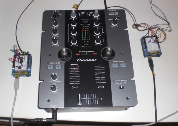
The process starts by generating a sine wave on an Arduino with some direct digital synthesis. A 480 Hz square wave is generated on an ATTiny85. Both of these signals are then fed into a 74LS08 AND gate. According to the schematic [Andy] posted, these signals are going into two different gates, with the other input of the gate pulled high. The output of the gate is then sent through a pair of resistors and combined to the ‘audio out’ signal. [Andy] says this is ‘spine-crawling’ for people who do this professionally. If anyone knows what this part of the circuit actually does, please leave a note in the comments.

The signal from the AND gates is then fed into the mixer and sent out to the analog input of another Arduino. This Arduino converts the audio coming out of the mixer to frequencies using a Fast Hartley Transform. With a binary representation of what’s happening inside the mixer, [Andy] has something that can be converted into MIDI.

[Andy] put up a demo of this circuit working. He’s connected the MIDI out to Abelton and can modify MIDI parameters using an audio mixer. Video of that below if you’re still trying to wrap your head around this one.

Continue reading “Digital To Analog To Digital To Analog To Digital Conversion”

The Smallest Portable Pi

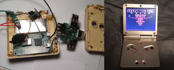
What do you get when you take an extremely small Raspberry Pi clone and stuff it inside a Game Boy Advance SP? We don’t know what to call it, but it’s probably one of the best portable gaming machines ever made, able to run emulators ranging from the Apple II to playing Quake III natively on a tiny flip-top display.

This isn’t the first time we’ve seen [frostedfires]’ work on a tiny system stuffed into a Game Boy. The initial post on this build over on the bacman forums just covered the basics – getting an Odroid W up and running, and putting Quake III on the tiny display. Now that the build is complete, we can get a look at what it takes to turn a Raspberry Pi clone into one of the smallest portable projects we’ve ever seen.

Using a Raspi clone as the only component in a tiny portable emulation station isn’t possible, so [frostefires] added a few other bits of electronics to make everything work. There’s a joystick from a PSP in there to work as the mouse, a few extra buttons in addition to the stock Game Boy ones, A USB hub, WiFi adapter, speaker and amplifier, a battery and the related charging electronics, and a Teensy 3.1 to handle all the input.

It’s a very impressive build that can run emulators ranging from the Apple II to later generation Nintendo consoles and handhelds (including the Game Boy Advance), but since the HDMI connector is availble on the outside of the case, [frostedfires] can also use this as a tiny, portable media center. Check out the video below to see this Game Boy in action, playing Mario Kart and 1080p video.

Continue reading “The Smallest Portable Pi”

Automatic 3D Scanning On The Cheap

After hearing about a few 3D object scanners, [Will] thought one of these tools could find a place in his workshop. The price of these scanners made him reconsider simply buying one, so he just made one out of parts that were sitting around. This was the first version of his 3D scanner. It worked, but there were a few shortcomings. [Will] had to rotate the object manually. That’s a cheap way of doing it, but the method is tedious.

Now [Will] is back for round two. He’s made some improvements, and this time a few bits of electronics automate the process, allowing [Will] to hit a button, walk away, and come back to a scanned object.

Even though [Will] has improved his setup immensely, the theory of how to scan an object remains the same. He’s projecting a straight vertical line on an object, taking a few snapshots with a webcam, and reconstructing the object with computer vision algorithms and Meshlab. The new additions include a BeagleBone Black, a stepper motor and an EasyDriver from Sparkfun, and a turntable.

[Will] wrote two scripts for this project. The first does the mechanical heavy lifting – turning the stepper motor and taking a picture, while the second converts the output from the webcam to a point cloud. From there, the point cloud is sent over to Meshlab, and an object appears on [Will]’s hard drive.

There’s about $80 in hardware invested in this setup, and considering the inspiration for this project was the $800 Makerbot Digitizer, we’re going to call [Will]’s experiments in 3D scanning a success.

Trinket EDC Contest: USB Calipers

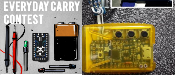
[Lou]’s entry for the Trinket EDC Contest is a great addition to the ubiquitous digital calipers found on workbenches and eBay resellers the world over. It translates the value displayed on the calipers to a USB HID interface for logging all those tricky measurements at the push of a button.

Most of the digital calipers you’ll find at Harbor Freight or on eBay are pretty much the same. There are two pads on the caliper’s PCB that give any microcontroller the ability to read what is being measured. It’s done with a 24-bit encoding scheme, where each bit is a nearly-BCD measurement in units of 1/1000 of an inch or 1/100 of a millimeter. After decoding the value, [Lou]’s trinket sends a few numbers to a computer over a USB HID interface.

Simply sending a measurement to a computer over USB wasn’t enough for [Lou]. He added three buttons to the project for typing multiple characters. The first button just sends Enter to the computer, the second sends a comma, and the third sends “/2 (Enter)”, exactly what you need to input the radius of something when measuring the diameter.

This was a project for the Trinket EDC Contest that ended a few hours ago. Nobody knows who the winner is, but there are some pretty cool prizes up for grabs including the new Rigol scope, a Fluke 179, and a soldering station.

Holiday Cheer From The ATtiny13

There are smaller microcontrollers than the ATtiny13. Some ARM chips will fit on the head of a large pin, and even in Atmel world, the ATtiny10 comes in a tiny SOT-23-6 package – a size normally reserved for surface mount transistors. The ‘tiny13, though, can be programmed with just about any ISP and comes in an 8-pin DIP. It’s the bare minimum if you’re looking to break out of the world of Arduino, and you can do some pretty cool things with it, like playing some holiday audio with an SPI Flash chip.

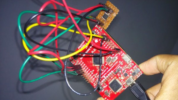
[Vinod] tried opening up a cheap camera pen, but in the course of disassembly a few traces broke. He was now left with a 4Mbit SPI Flash chip. This was obviously the time to investigate what could be done with a small microcontroller and a huge amount of Flash. and the Attiny13 audio player was born.

The circuit uses one PWM for audio out, and reads audio directly from the Flash chip. The UART on board the ‘tiny13 is used to update the Flash, and there’s also a switch to select between play and record. If you’re counting, that means there are 4 pins for the Flash, 2 pins for the UART, 1 for the switch, one for the audio output, and the power and ground rails, all in an 8-pin package. That’s a pretty cool way to use one pin for two different functions.

You can check out a video of the project in action below.

Continue reading “Holiday Cheer From The ATtiny13”