PCB internal bodge

PCB Microsurgery Puts The Bodges Inside The Board

We all make mistakes, and there’s no shame in having to bodge a printed circuit board to fix a mistake. Most of us are content with cutting a trace or two with an Xacto or adding a bit of jumper wire to make the circuit work. Very few of us, however, will decide to literally do our bodges inside the PCB itself.

The story is that [Andrew Zonenberg] was asked to pitch in debugging some incredibly small PCBs for a prototype dev board that plugs directly into a USB jack. The six-layer boards are very dense, with a forest of blind vias. The Twitter thread details the debugging process, which ended up finding a blind via on layer two shorted to a power rail, and another via shorted to ground. It also has some beautiful shots of [Andrew]’s “mechanical tomography” method of visualizing layers by slowly grinding down the surface of the board.

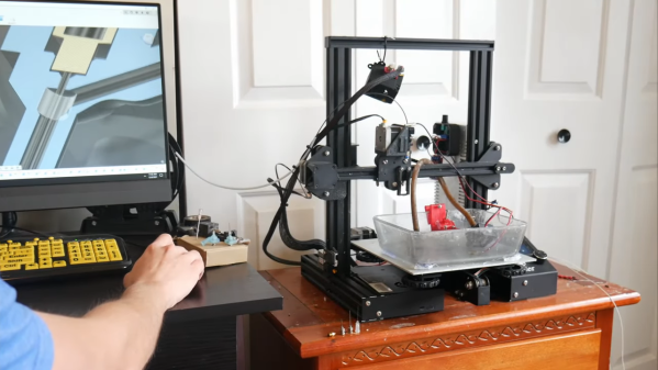
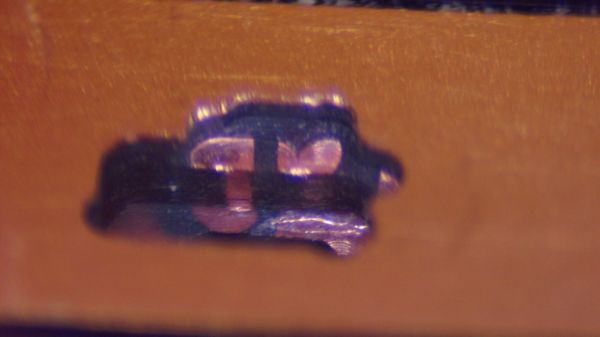
[Andrew] has only tackled one of the bodges at the time of writing, but it has to be seen to be believed. It started with milling away the PCB to get access to the blind via using a ridiculously small end mill. The cavity [Andrew] milled ended up being only about 480 μm by 600 μm and only went partially through a 0.8-mm thick board, but it was enough to resolve the internal short and add an internal bodge to fix a trace that was damaged during milling. The cavity was then filled up with epoxy resin to stabilize the repair.

This kind of debugging and repair skill just boggles the mind. It reminds us a bit of these internal chip-soldering repairs, but taken to another level entirely. We can’t wait to see what the second repair looks like, and whether the prototype for this dev board can be salvaged.

Thanks to [esclear] for the heads up on this one.

Bed of nails

Design For Test Hack Chat

Join us on Wednesday, December 15 at noon Pacific for the Design for Test Hack Chat with Duncan Lowder!

If your project is at the breadboard phase, or even if you’ve moved to a PCB prototype, it’s pretty easy to know if it works. It either does what it’s supposed to do, or it doesn’t, and a few informal tests will probably tell you all you need to know. But once you scale up to production, the testing picture becomes quite different. How do you know you’re not shipping out a problem? And how do you make sure your testing process doesn’t become a bottleneck?

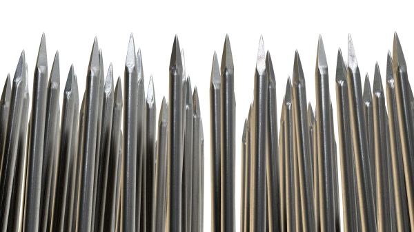
Answering questions like these can be difficult, which is why we’ve invited Duncan Lowder to come talk with us. He was a test lead at places like Glowforge and Sphero before founding FixturFab, where he’s working on ways to make hardware testing as easy as possible, no matter what scale you’re working at. We’ll learn all about how to make our designs easy to test right from the get-go and take the pain out of that bed of nails.

join-hack-chatOur Hack Chats are live community events in the Hackaday.io Hack Chat group messaging. This week we’ll be sitting down on Wednesday, December 15 at 12:00 PM Pacific time. If time zones have you tied up, we have a handy time zone converter.

Wire race bearing

Adding Wire Races Improves 3D-Printed Bearings

Like a lot of power transmission components, bearings have become far easier to source than they once were. It used to be hard to find exactly what you need, but now quality bearings are just a few clicks away. They’re not always cheap though, especially when you get to the larger sizes, so knowing how to print your own bearings can be a handy skill.

Of course, 3D-printed bearings aren’t going to work in every application, but [Eros Nicolau] has a plan for that. Rather than risk damage from frictional heating by running plastic or metal balls in a plastic race, he uses wire rings as wear surfaces. The first video below shows an early version of the bearing, where a pair of steel wire rings lines the 3D-printed inner and outer races. These worked OK, but suffered from occasional sticky spots and were a bit on the noisy side.

The second video shows version two, which uses the same wire-ring race arrangement but adds a printed ball cage to restrain the balls. This keeps things quieter and eliminates binding, making the bearing run smoother. [Eros] also added a bit of lube to the bearing, in the form of liquid PTFE, better known as Teflon. It certainly seemed to smooth things out. We’d imagine PTFE would be more compatible with most printed plastics than, say, petroleum-based greases, but we’d be keen to see how the bearings hold up in the long term.

Maybe you recall seeing big 3D-printed bearings around here before? You’d be right. And we’ve got you covered if you need to learn more about how bearings work — or lubricants, for that matter.

Continue reading “Adding Wire Races Improves 3D-Printed Bearings”

Mining And Refining: From Red Dirt To Aluminum

No matter how many syllables you use to say it, aluminum is one of the most useful industrial metals we have. Lightweight, strong, easily alloyed, highly conductive, and easy to machine, cast, and extrude, aluminum has found its way into virtually every industrial process and commercial product imaginable.

Modern life would be impossible without aluminum, and yet the silver metal has been in widespread use only for about the last 100 years. There was a time not all that long ago that aluminum dinnerware was a status symbol, and it was once literally worth more than its weight in gold. The reason behind its one-time rarity lies in the effort needed to extract the abundant element from the rocks that carry it, as well as the energy to do so. The forces that locked aluminum away from human use until recently have been overcome, and the chemistry and engineering needed to do that are worth looking into in our next installment of “Mining and Refining.”

Continue reading “Mining And Refining: From Red Dirt To Aluminum”

Hackaday Links Column Banner

Hackaday Links: December 12, 2021

It looks as though the Mars Ingenuity flight team is starting to press the edge of the envelope a bit. The tiny rotorcraft, already 280-something sols into a mission that was only supposed to last for about 30 sols, is taking riskier flights than ever before, and things got particularly spicy during flight number 17 this past week. The flight was a simple up-over-and-down repositioning of the aircraft, but during the last few meters of descent at its landing zone, Ingenuity dipped behind a small hill and lost line-of-sight contact with Perseverance. Without the 900-MHz telemetry link to the rover, operators were initially unable to find out whether the chopper had stuck the landing, as it had on its previous 16 flights. Thankfully, Perseverance picked up a blip of data packets about 15 minutes after landing that indicated the helicopter’s battery was charging, which wouldn’t be possible if the craft were on its side. But that’s it as far as flight data, at least until they can do something about the LOS problem. Whether that involves another flight to pop up above the hill, or perhaps even repositioning the rover, remains to be decided.

Thinking up strong passwords that are memorable enough to type when they’re needed is never easy, and probably contributes more to the widespread use of “P@$$w0rD123” and the like than just about anything. But we got a tip on a method the musically inclined might find useful — generating passwords using music theory. It uses standard notation for chords to come up with a long, seemingly random set of characters, like “DMaj7|Fsus2|G#9”. It’s pretty brilliant, especially if you’ve got the musical skills to know what that would sound like when played — the rest of us can click here to find out. But since we can’t carry a tune in a bucket, we’ll just stick with the “correct horse battery staple” method.

Looks like you can only light so many roofs on fire before somebody starts to take an interest in what’s going on. At least that seems to be the case with Tesla, which is now under investigation by the US Security and Exchanges Commission for not keeping its shareholders and the public looped in on all those pesky solar array fires it was having back in the day. The investigation stems from a 2019 whistleblower complaint by engineer Steven Henkes, who claims he was fired by Tesla after pointing out that it really would be best not to light their customers’ buildings on fire with poorly installed solar arrays. It’s interesting that the current investigation has nothing to do with the engineering aspects of these fires, but rather the financial implications of disclosure. We discussed some of those problems before, which includes dodgy installation practices and seems to focus on improperly torqued MC4 connectors.

Staying with the Tesla theme, it looks like the Cybertruck is going to initially show up as a four-motor variant. The silly-looking vehicle is also supposed to sport four-wheel steering, which will apparently make it possible to drive diagonally. We’ve been behind the wheel for nearly four decades at this point and can count on no hands the number of times diagonal driving would have helped, and while there might be an edge case we haven’t bumped into yet, we suspect this is more about keeping up with the competition than truly driving innovation. It seems like if they were really serious about actually shipping a product, they’d work on the Cybertruck windshield wiper problem first.

And finally, as I’m sure you’re all aware by now, our longtime boss Mike Szczys is moving on to greener pastures. I have to say the news came as a bit of shock to me, since I’ve worked for Mike for over six years now. In that time, he has put me in the enviable position of having a boss I actually like, which has literally never happened to me before. I just thought I’d take the chance to say how much I appreciate him rolling the dice on me back in 2015 and giving me a chance to actually write for a living. Thanks, Mike, and best of luck with the new gig!

DIY castellated PCB connectors

Snip Your Way To DIY PCB Castellations

Castellated PCB edges are kind of magical. The plated semicircular features are a way to make a solid, low-profile connection from one board to another, and the way solder flows into them is deeply satisfying. But adding them to a PCB design isn’t always cheap. No worries there — you can make your own castellations with this quick and easy hack.

Scissors cutting a PCB through vias to make castellations[@CoilProtogen] doesn’t include much information in the Twitter thread about design details, but the pictures make it clear what the idea is here. OEM castellations are really just plated areas at the edge of a board that can be used to tack the board down to another one without any added hardware. The hack here is realizing that lining up a bunch of large-diameter vias and cleaving them in half with a sharp pair of scissors will result in the same profile without the added cost. The comments on the thread range from extolling the brilliance of this idea to cringing over the potential damage to the board, but [@CoilProtogen] insists that the 0.6-mm substrate cuts like butter. We’d worry that the plating on the vias would perhaps tear, but that seems not to be the case here.

The benefits of a zero-profile connection are pretty clear in this case, where castellated PCBs were used to replace bulky header-pin connectors on a larger PCB. We can see this technique being generally useful; we’ve seen them used to good effect before, and this is a technique we’ll keep in mind for later.

Epoxy lenses

The Ins And Outs Of Casting Lenses From Epoxy

If you need a lens for a project, chances are pretty good that you pick up a catalog or look up an optics vendor online and just order something. Practical, no doubt, but pretty unsporting, especially when it’s possible to cast custom lenses at home using silicone molds and epoxy resins.

Possible, but not exactly easy, as [Zachary Tong] relates. His journey into custom DIY optics began while looking for ways to make copies of existing mirrors using carbon fiber and resin, using the technique of replication molding. While playing with that, he realized that an inexpensive glass or plastic lens could stand in for the precision-machined metal mandrel which is usually used in this technique. Pretty soon he was using silicone rubber to make two-piece, high-quality molds of lenses, good enough to try a few casting shots with epoxy resin. [Zach] ran into a few problems along the way, like proper resin selection, temperature control, mold release agent compatibility, and even dealing with shrinkage in both the mold material and the resin. But he’s had some pretty good results, which he shares in the video below.

[Zach] is clear that this isn’t really a tutorial, but rather a summary of the highs and lows he experienced while he was working on these casting methods. It’s not his first time casting lenses, of course, and we doubt it’ll be his last — something tells us he won’t be able to resist trying this all-liquid lens casting method in his lab.

Continue reading “The Ins And Outs Of Casting Lenses From Epoxy”