Logic Meter Aims To Make Hobby Electronics Troubleshooting Easier

The basic test instrument suite — a bench power supply, a good multimeter and perhaps an oscilloscope — is extremely flexible, but not exactly “plug and play” when it comes to diagnosing problems with some common hardware setups. A problem with a servo driver, for example, might be easy enough to sort of with a scope, but setting everything up to see what’s going on with the PWM signal takes some time.

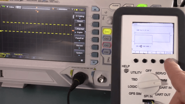
There’s got to be a better way to diagnose hobby electronics woes, and if [Bob Alexander] has his way, his “Logic Meter”, or something very close to it, will be the next must-have bench tool. The Logic Meter combines some of the functionality of an oscilloscope and a logic analyzer into a handy instrument that’s as easy to use as a multimeter. The Logic Meter’s probes connect to logic-level signals in a circuit and can be set up to capture or send serial data, either directly to or from a UART or via an SPI bus connection. There are also functions for testing servos and similar devices with a configurable PWM output. [Bob] rounds out the functionality with a GPS simulator and a simple logic analyzer, plus some utility functions.

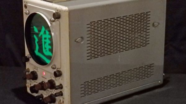
The beauty part of the Logic Meter is that [Bob] has left where it goes next largely up to the community. He’s got a GitHub repo with details on the PIC32-based hardware, and the video below makes it clear that this is just a jumping-off point to further work that he hopes results in a commercial version of the Logic Meter. That’s a refreshing attitude, and we hope it pays off; from the look of a few of [Bob]’s retrocomputing makeovers, something like the Logic Meter could come in pretty handy.

Continue reading “Logic Meter Aims To Make Hobby Electronics Troubleshooting Easier”

Linear Pong Loses A Dimension But Remains Challenging

When Pong hit the scene in the early 70s, there was something about the simplicity of the 2D monochrome tennis game that made it engaging enough that enthusiastic proto-gamers shorted-out machines by stuffing their coin boxes to overflowing.  But even with the simplicity of Pong’s 2D gameplay, the question becomes: could it by made simpler and still be playable?

Surprisingly, if this one-dimensional Pong game is any indication, it actually seems like it can. Where the original Pong made you line up your paddle with the incoming ball, with the main variable being the angle of the carom from your opponent, [mircemk]’s version, limited to a linear game field, makes the ball’s speed the variable. Players take control of the game with a pair of buttons at the far ends of a 60-LED strip of WS2812s. The ball travels back and forth along the strip, bouncing off a player’s paddle only if they push their button at the exact moment the ball arrives. Each reflection back to the opponent occurs at a random speed, making it hard to get into a rhythm. To add some variety, each player has a “Boost” button to put a little spice on their shot, and score is kept by LEDs in the center of the play field. Video of the game play plus build info is below the break.

With just a Neopixel strip, an Arduino Nano, and a small handful of common parts, it should be easy enough to whip up your own copy of this surprisingly engaging game. But if the 2D-version is still more your speed, maybe you should check out the story of its inventor, [Ted Dabney]. Or, perhaps building a clock that plays Pong with itself to idle the days away is more your speed.

Continue reading “Linear Pong Loses A Dimension But Remains Challenging”

ESP32-S2 And RP2040 Hack Chat With Adafruit

Join us on Wednesday, January 27 at noon Pacific for the ESP32-S2 and RP2040 Hack Chat with Adafruit!

It’s always an event when we have Adafruit on the Hack Chat, and last time was no exception. Then, the ESP32-S2 was the new newness, and Adafruit was just diving into what’s possible with the chip. It’s an interesting beast — with a single core and no Bluetooth or Ethernet built-in, it appears to be less capable than other Espressif chips. But with a faster CPU, more GPIO and ADCs, a RISC-V co-processor, and native USB, the chip looked promising.

Among their other duties, the folks at Adafruit have spent the last six months working with the chip, and they’d now like to share what they’ve learned with the community. So Limor “Ladyada” Fried, Phillip Torrone, Scott Shawcroft, Dan Halbert, and Jeff Epler will stop by the Hack Chat to show us what’s under the hood of the ESP32-S2. They’ve worked on a bunch of projects using the chip, and they’ve taken a deep-dive into the chip’s deep-sleep capabilities, so stop by the Chat with your burning questions about low-power applications or anything ESP32-S2-related and ask away.

Plus, a late and exciting addition to the agenda: they’ll be talking about the recently released RP2040, the first custom chip from the folks at Raspberry Pi. We’ve already started talking about the Raspberry Pi Pico​, the dev board that uses the chip, and Adafruit will share what they’ve learned about the RP2040 so far.

join-hack-chatOur Hack Chats are live community events in the Hackaday.io Hack Chat group messaging. This week we’ll be sitting down on Wednesday, January 27 at 12:00 PM Pacific time. If time zones have you tied up, we have a handy time zone converter.

Click that speech bubble to the right, and you’ll be taken directly to the Hack Chat group on Hackaday.io. You don’t have to wait until Wednesday; join whenever you want and you can see what the community is talking about.

Continue reading “ESP32-S2 And RP2040 Hack Chat With Adafruit”

Hackaday Links Column Banner

Hackaday Links: January 24, 2021

Code can be beautiful, and good code can be a work of art. As it so happens, artful code can also result in art, if you know what you’re doing. That’s the idea behind Programming Posters, a project that Michael Fields undertook to meld computer graphics with the code behind the images. It starts with a simple C program to generate an image. The program needs to be short enough to fit legibly into the sidebar of an A2 sheet, and as if that weren’t enough of a challenge, Michael constrained himself to the standard C libraries to generate his graphics. A second program formats the code and the image together and prints out a copy suitable for display. We found the combination of code and art beautiful, and the challenge intriguing.

It always warms our hearts when we get positive feedback from the hacker community when something we’ve written has helped advance a project or inspire a build. It’s not often, however, that we learn that Hackaday is required reading. Educators at the Magellan International School in Austin, Texas, recently reached out to Managing Editor Elliot Williams to let him know that all their middle school students are required to read Hackaday as part of their STEM training. Looks like the kids are paying attention to what they read, too, judging by KittyWumpus, their ongoing mechatronics/coding project that’s unbearably adorable. We’re honored to be included in their education, and everyone in the Hackaday community should humbled to realize that we’ve got an amazing platform for inspiring the next generation of hardware hackers.

Hackers seem to fall into two broad categories: those who have built a CNC router, and those who want to build one. For those in the latter camp, the roadblock to starting a CNC build is often “analysis paralysis” — with so many choices to make, it’s hard to know where to start. To ease that pain and get you closer to starting your build, Matt Ferraro has penned a great guide to planning a CNC router build. The encyclopedic guide covers everything from frame material choice to spindle selection and software options. If Matt has a bias toward any particular options it’s hard to find; he lists the pros and cons of everything so you can make up your own mind. Read it at your own risk, though; while it lowers one hurdle to starting a CNC build, it does nothing to address the next one: financing.

Like pretty much every conference last year and probably every one this year, the Open Hardware Summit is going to be virtual. But they’re still looking for speakers for the April conference, and just issued a Call for Proposals. We love it when we see people from the Hackaday community pop up as speakers at conferences like these, so if you’ve got something to say to the open hardware world, get a talk together. Proposals are due by February 11, so get moving.

And finally, everyone will no doubt recall the Boston Dynamics robots that made a splash a few weeks back with their dance floor moves. We loved the video, mainly for the incredible display of robotic agility and control but also for the choice of music. We suppose it was inevitable, though, that someone would object to the Boomer music and replace it with something else, like in the video below, which seems to sum up the feelings of those who dread our future dancing overlords. We regret the need to proffer a Tumblr link, but the Internet is a dark and wild place sometimes, and only the brave survive.

https://commiemartyrshighschool.tumblr.com/post/640760882224414720/i-fixed-the-audio-for-that-boston-dynamics-video

A Deep Dive Into The Chemistry Of Retrobright

Considerable effort is often required to rejuvenate the yellowed and grungy plastic cases of retrocomputing gear. One generally does well to know their enemy in order to fight it, though, which is where this guide to the chemistry of plastic yellowing and whitening (PDF) comes in handy.

“The Retrobright Mystery” was written and sent in to us by [Caden Xu], a high school student who also goes by the alias [Saltypretzel]. The paper begins with an excellent description of the chemistry of plastic yellowing. We had always heard that the yellowing in ABS, or acrylonitrile-butadiene-styrene, the plastic most commonly used for cases back in the day, was primarily caused by brominated compounds added to the plastic as flame retardants. It turns out that’s only a minor contributor, with the bulk of yellowing occurring thanks to a complex chain of reactions starting with free radicals liberated from the butadiene copolymer through a reaction requiring oxygen and energy.

Reactive radicals from the decomposing synthetic rubber, added to ABS to increase its flexibility, unroll the benzene ring in styrene copolymers to form a conjugated compound called 2-hydroxymuconic acid. The alternating double and single bonds in this compound tend to absorb light towards the blue end of the spectrum strongly, so the accumulation of 2-HMA in the plastic over time thus makes it reflect more and more yellow and red wavelengths, giving aged ABS its unhealthy bronze glow.

Luckily, just as ketchup smears and grass stains, both rich in conjugated compounds like lycopene and chlorophyll, can be bleached out of existence, so too can yellowed plastics. [Caden] notes that Retrobright, which contains a powerful dose of hydrogen peroxide, does its whitening trick by breaking the UV-absorbing double bonds in 2-HMA. There’s little that can be done about the embrittlement of the ABS caused by the breakdown of butadiene copolymers, but at least it’ll look good.

We found this guide quite comprehensive and instructive, and it should only help retrocomputing fans in their restoration efforts. For those less interested in the chemistry, [Bob Baddeley] published an overview of the yellowing of plastic and manufacturing steps to avoid it, and we covered the more practical considerations of Retrobright treatment too.

A One-Transistor Ham Transmitter Anyone Can Build

What attracts a lot of people to amateur radio is that it gives you the ability to make your own gear. Scratch-building hams usually start by making their own antennas, but eventually, the itch to build one’s own radio must be scratched. And building this one-transistor transmitter is just about the simplest way to dive into the world of DIY radio.

Of course, limiting yourself to eight components in total entails making some sacrifices, and [Kostas (SV3ORA)]’s transmitter is clearly a study in compromise. For starters, it’s only a transmitter, so you’ll need to make other arrangements to have a meaningful conversation. You’ll also have to learn Morse code because the minimalist build only supports continuous-wave (CW) mode, although it can be modified for amplitude modulation (AM) voice work.

The circuit is flexible enough that almost any part can be substituted and the transmitter will still work. Most of the parts are junk-bin items, although the main transformer is something you’ll have to wind by hand. As described, the transformer not only provides feedback to the transistor oscillator, but also has a winding that powers an incandescent pilot lamp, and provides taps for attaching antennas of different impedances — no external tuner needed. [SV3ORA] provides detailed transformer-winding instructions and shows the final build, which looks very professional and tidy. The video below shows the rig in action with a separate receiver providing sidetone; there’s also the option of using one of the WebSDR receivers sprinkled around the globe to verify you’re getting out.

This little transmitter looks like a ton of fun to build, and we may just try it for our $50 Ham series if we can find all the parts. Honestly, the hardest to come by might be the variable capacitor, but there are ways around that too.

Continue reading “A One-Transistor Ham Transmitter Anyone Can Build”

Oscilloscope Learns How To Speak Japanese, And VGA

Nostalgia aside, there are a few things an analog scope can still do better than a digital, with oscilloscope art being a prime example. The blue-green glow of phosphors in a real CRT just add something special to such builds, and as a practitioner of this craft, [Aaron] decided to paint a New Year’s affirmation on his oscilloscope screen, in Japanese calligraphy of all things.

When used in X-Y mode, analog oscilloscopes lend themselves nicely to vector-based graphics, which is the approach [Aaron] has taken with previous “Oscilloclock” builds, like the Metropolis Clock. The current work, however, doesn’t use vector graphics, opting instead to turn the scope into the business end of a VGA display. He had previously developed the hardware needed to convert a VGA signal into X- and Y-axis analog outputs, so the bulk of the work was rendering the calligraphy, first in ink and then scanning and processing the results into a file. In keeping with the Japanese theme, [Aaron] chose a rare scope from Nihon Tsushinki Co., Ltd., from 1963. It’s a beautiful piece of equipment and obviously lovingly restored, and with the VGA adapter temporarily connected, the four Japanese characters scroll gracefully up the screen, delivering the uplifting message: “Steady progress, day by day.

[Aaron] sure puts a lot of work into his analog scope builds, which we’ve featured a few times. Check out the clock he made from Grandpa’s old Heathkit scope, or his Tektronic vectorscope clock. And don’t forget about other forms of oscilloscope art — they can make music too, after all.