We are used to imagining radio telescopes as immense pieces of scientific apparatus, such as the Arecibo Observatory in Puerto Rico, or the Lovell telescope in the UK. It’s a surprise then that they can be constructed on a far more modest sale using off-the-shelf components, and it’s a path that [Gonçalo Nespral] has taken with his tiny radio telescope using a satellite dish. It’s on an azimuth-elevation mount using an Ikea lazy susan and a lead screw, and it has a satellite TV LNB at the hot end with a satellite finder as its detector.
So far he’s managed only to image the wall of his apartment, but that clearly shows the presence of the metal supporting structure within it. Taking it outdoors has however not been such a success. If we wanted to hazard a guess as to why this is the case, we’d wish to look at the bandwidth of that satellite finder. It’s designed to spot a signal from a TV broadcast bird over the whole band, and thus will have a bandwidth in the hundreds of MHz and a sensitivity that could at best be described as a bit deaf. We hope he’ll try a different path such as an RTL-SDR in the future, and we look forward to his results.
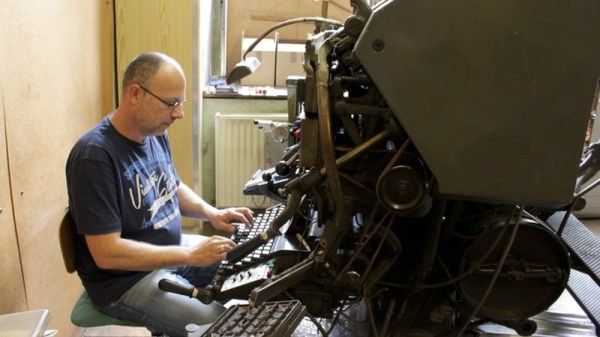
The journalist’s art is now one of the computer keyboard and the internet connection, but there was a time when it involved sleepless nights over a manual typewriter followed by time spent reviewing paper proofs freshly inked from hot lead type. Newspapers in the golden age of print media once had entire floors of machinery turning text into custom metal type on the fly, mechanical masterpieces in the medium of hot lead of which Linotype were the most famous manufacturer.
Computerised desktop publishing might have banished the Linotype from the newsroom in the 1970s or 1980s, but a few have survived. One of the last working Linotypes in Europe can be found in a small print workshop in Vienna, and since its owner is about to retire there is a move to save it for posterity through a crowdfunding campaign. This will not simply place it in a museum as a dusty exhibit similar to the decommissioned Monotype your scribe once walked past every day in the foyer of the publishing company she then worked for, instead it will ensure that the machine continues to be used on a daily basis producing those hot metal slugs of type.
Fronting the project is [Florian Kaps], whose pedigree in the world of resurrecting analogue technologies was established by his role in saving the Polaroid film plant in Enschede, Netherlands. There are a variety of rewards featuring Linotype print, and at the time of writing the project is 46% funded with about four weeks remaining. If you are curious about the Linotype machine and its operation, we’ve previously brought you an account of the last day of hot metal printing at the New York Times.
The breadboard microcontroller experimenter has a host of platforms to work with that can be had in the familiar DIP format. Old-school people can still find classic 8-bit platforms, the Ardunisti have their ATMegas, and PIC lovers have a pile of chips to choose from. But ARM experimenters? Out of luck, because as we have previously reported, popular past devices such as the LPC810 in a DIP8 package are now out of production.
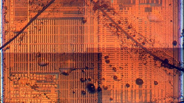
News comes from China though of a tiny ARM Cortex M0 for pennies that may not be in a DIP8, but is in almost the next best thing. The Synwit SWM050 can be had in a TSOP8, which though it’s not quite as friendly as its larger SOIC8 cousin, is still easily solderable onto a DIP8 adaptor for breadboard use. Spec-wise it’s 5 V tolerant, has an 8 kB FLASH and 1 kB of RAM, 6 GPIOs, and can clock away at a not incosequential 36 MHz.
We have [Sjaak] to thank for the discovery of this device, and for doing a lot of work including getting some die shots taken to dig up and make sense of the Chinese documentation, and to provide some dev tools should anyone want to play with it. There’s even a small breakout board for the experimenter unwilling to design their own.
Earlier this year we marked the passing of the DIP8 version of the LPC810 microcontroller, and for those mourning it we made an important point. It’s now normal to use one of the vast array of single board computers instead of a bare microcontroller, you might wish to ask yourself why you would do so.
Nearly a decade ago my friend [Dru] gave me an unforgettable tour late at night of Stokes Croft, the inner suburb of Bristol known at the time for its counterculture and artistic scene. It’s a place dominated by building-sized graffiti and murals, and it has a particular association with the Bristolian street artist [Banksy]. If you’ve not seen a Banksy in the wild, the place to do it is by Bristol Saturday night street lighting to the sound of passing revelers and traffic on the A38.
[Banksy] is famous aside from his anonymity, for his pranks upon the art world. The (real) elephant in the room or the Dismalland theme park are his stock in trade, and you may have seen another prank of his in the news in the last day. One of his paintings, the 2006 Girl With A Balloon sold at auction for over a million quid, and as the gavel fell a hidden shredder in the picture frame sprang into life and partially shredded the canvas. The report suggests that a number of [Banksy]’s associates were present at the event, and that one of them was detained with a device that might have been a remote control trigger for the shredder. The quote from Sotheby’s Europe head of Contemporary Art, [Alex Branczik] says it all: “We got Banksy’d”.
The interior of the Banksy shredder frame, taken from a frame of the video.
[Banksy]’s cool and all that, but where’s the hack? The artist briefly put up a video with a few details, but aside from showing us a row of craft knife blades and a tantalizing but fleeting glimpse of a few equipment enclosures, it’s short on technical details. We can see what appears to be at least one motor, and those white boxes may be batteries, but that’s it.
This hasn’t stopped some fevered speculation as to how the feat was achieved. A home-made shredder would require a significant amount of readily available power, and since this one has seemingly lain undetected within the frame since 2006, that power source needs to have possessed both exceptional energy density and retention. We can’t imagine many consumer grade batteries in 2018 being able to retain a charge for twelve years, so how on earth did he do it? Our best guess is that a primary battery was involved, as anyone who has found a neglected Duracell in a box of electronics from their youth will tell you it’s not unknown for decent quality alkaline cells to live well beyond their shelf lives, and other chemistries are specifically designed with that property in mind. Even so, for the cells to power a receiver circuit in standby for so long would certainly tax their capabilities, so it has also been suggested that a concealed switch could have been flipped by a [Banksy] accomplice during the viewing phase to activate the system. There are still so many unanswered questions that it’s certainly piqued our technical curiosity. Sadly we don’t know [Banksy] to ask him how he did it, but we welcome speculation both informed and otherwise in the comments.
Our own [Joe Kim]’s tribute to the work in question.Meanwhile the piece itself lies half shredded and protruding from the base of the frame. On the face of it that’s ruined the painting as an artwork, but of course this is a Banksy. Normal rules seem not to apply, so the notoriety it has received will no doubt mean that its shredded remains are an artwork in themselves, and possibly even one worth more.
Banksy owners worldwide are no doubt now paying a huge amount more attention to the artist’s frames than previously, but Hackaday readers need not worry. Our London Unconference logo and stickers featured a [Joe Kim] homage to the Banksy in question, which we can guarantee does not incorporate an artist’s shredder.
If you were lucky enough to own one of the crop of 1980s 8-bit computers, did you ever pause to consider how its graphics worked? Maybe the really expensive ones had dedicated CRT controller subsystems akin to the graphics cards you’d have found on a PC a few years later, but most of the affordable models would have stopped what they were doing every TV line interval period to allow access to their memory for their graphical output to be created.
The RC2014 retrocomputer dodges all this, by using a serial port as an interface and expecting your serial terminal to handle the screen. But what if it could produce its graphics directly as the machines of old did? [Rob Dobson] set out to achieve this, and not only did he succeed but he also found a way to directly emulate some classic machines along the way.
His RC2014 card which he calls the Bus Raider started as an attempt to use a Raspberry Pi to commandeer the RC2014 memory and read it via its GPIO lines, interpreting the graphics for its own screen. But even with bare metal Pi programming he couldn’t achieve the complex timing required for that, so he took an alternative approach. He ended up with an ESP32 that emulates a custom part of the RC2014 memory map and generates a display from there. Having created a custom memory map and hardware emulator for his RC2014, he then had the revelation that he could emulate any memory map, and thus he could make the retrocomputer perform natively as though it were any of a selection of classic micros. So far as well as a straight serial terminal he has a Sinclair ZX Spectrum and a Radio Shack TRS-80 running, as well as his own custom Z80 environment. And since the ESP32 also has WiFi, he can even connect to it through that medium.
Retrocomputers are something in which you might think that everything possible would already have been done, but projects like this one never cease to amaze us with their ingenuity. If you’d like to read more about the RC2014, we reviewed an earlier model back in 2016.
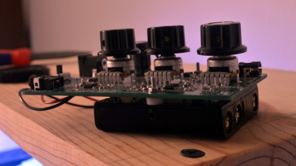
There was a time when any hi-fi worth its salt had a little row of sliders on its front panel, a graphic equalizer. On a hi-fi these arrays of variable gain notch filters were little more than a fancy version of a tone control, but in professional audio and PA systems they are used with many more bands to precisely equalise a venue and remove any unwanted resonances.
On modern hi-fi the task is performed in software, but [Grant Giesbrecht] wanted an analogue equalizer more in the scheme of those fancy tone controls than the professional devices. His project makes for a fascinating foray into analogue filter design, as well as an understanding of how an equalizer combines multiple filters. Unexpectedly their outputs are not mixed because it proves surprisingly difficult to ensure all the filters have the same gain, instead they are in series with the signal path passing through all filters.
The resulting equalizer is neatly built upon a PCB with a 4-AA-cell power supply, and makes for a self-contained audio component. Unexpectedly such analogue equalizer have been few and far between here at Hackaday so it’s particularly pleasing to see. We’re more used to graphical displays for off-the-shelf devices.
This summer’s Electromagnetic Field hacker camp in a field in western England gave many of the European side of our community their big fix of cool stuff for the year.
Some lucky individuals can spend the year as perpetual travelers, landing in a new country every week or so for the latest in the global round of camps. For the rest of us it is likely that there will be one main event each year that is the highlight, your annual fill of all that our global community has to offer. For many Europeans the main event was the biennial British event, Electromagnetic Field. From a modest start in 2012 this has rapidly become a major spectacle, one of the ones to include in your calendar, delivered both for our community and by our community.


![Our own [Joe Kim]'s tribute to the work in question.](https://hackaday.com/wp-content/uploads/2017/07/london.jpg)